
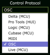
External Control
The SSL Live console is capable of remotely controlling other devices over its Connectivity network ports. This allows tighter integration between different parts of a wider system, such as a loudspeaker processing unit downstream of the console.
Instructions for the configuration of supported devices are provided below.
Console OSC Paths
Devices may be controlled either via console audio paths or through dedicated 'OSC' (Open Sound Control) paths on the console, depending on the device under control. OSC paths have no audio processing capability but can be placed on the console surface like other path types, allowing external device control to be easily integrated into your workflow.
A section in the Console Configuration page (MENU > Setup > Console Configuration) is provided for adding OSC paths if required. Refer to the Console Configuration section for further details on using this page.
Sigma Setup
Download and install the Sigma Remote application to your Mac or PC using the instructions provided in the User Manual here .
Set the protocol to OSC in the Settings page of the application; refer to the User Manual for instructions.
Ensure the Sigma's IP address is set appropriately for your network. Sigma's default IP address is 192.168.1.201/24.
Once configured the Sigma Remote application can be closed; it does not need to be running to use Sigma with OSC.
Console Setup
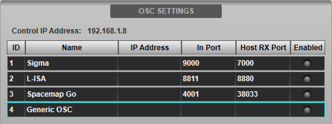
Navigate to the console's External Control options tab (MENU > Setup > Options). Tap Sigma in the device list in the OSC SETTINGS section of the page.
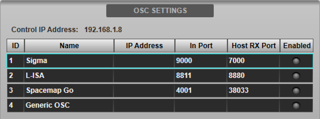
Double-tap the Host IP Address field in the DEVICE CONFIGURATION section below and enter the IP Address of the Sigma. The Name, Incoming Port and Host RX Port fields are read-only and for information only.

The IP address entered will be stored in the showfile. Note that each IP address on the network must be unique. The console's IP address is also displayed in this page for reference.
The console's IP address must be in the same subnet as (but not identical to) the IP address of the Sigma and can be changed in the Network options tab (MENU > Setup > Options > Network tab; see Network Options for more details).
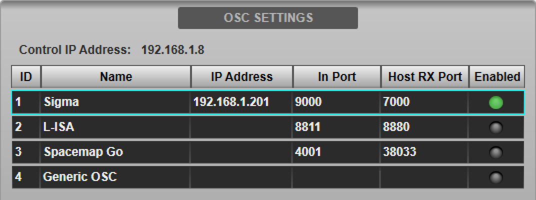
Press the Enable Control button to enable control of Sigma from the console. The Enabled indicator in the device list will light green. Multiple devices can be enabled simultaneously.
Creating Console OSC Paths
Create one OSC Path in the Console Configuration page (MENU > Setup > Console Configuration) for each Sigma channel you wish to control. Refer to the Console Configuration section for further details on using this page.
Path Assignment
Place the OSC Paths on the surface using the Layer Manager. These may be placed in banks as desired, just like any other path type. Depending on the workflow desired, a dedicated bank could be created, or OSC Paths can be interspersed with other console paths.
Navigate to the OSC Paths in the Channel View and double-tap the Eyeconix area at the bottom of the screen to open the Name/Eyeconix Detail View page. Name/colour the OSC Paths as desired.
Navigate to the External Control Detail View page and select Sigma from the Select Device menu.
When communicating with Sigma, the displayed OSC Path number will be used as the Sigma channel number to control. The Control Path Num Offset field in the External Control Detail View page can be used to apply an offset to the path number. E.g. if console OSC Path 8 is to control Sigma channel 4, an offset of -4 must be entered. Path Link can be used to assign Sigma and apply offsets to multiple OSC Paths simultaneously. The selected device and offset per path will be stored in the showfile.
Note: Care should be taken when setting the Control Path Num Offset field that the same Sigma channel is not accessed via more than one console path.Parameters within OSC Paths can be automated in the same way as other path types; use the Automation Filters to adjust the store and recall scope.
Available Controls
From the Fader Tile hardware and various Fader sections of the GUI (Detail View, Channel View etc.) the control path's Fader, Solo and Mute controls will respectively alter the Gain, Solo and Cut functions of the mapped Sigma channel.
OSC Paths are also remotely controllable from SOLSA and TaCo.
Introduction
SSL and L-Acoustics have worked closely to deliver tightly integrated control of L-ISA immersive loudspeaker systems from the console interface. L-ISA sources can be associated with mono or stereo console Channels or Stems, with full control of L-ISA Pan, Distance, Width, Elevation and Aux Send level for each source available from the console.
Note: This feature is only available when running console software version 4.11 and above and L-ISA Controller software version 2.2.2 and above.L-ISA Controller Setup
Open the L-ISA Controller software and navigate to the DeskLink Settings page (Settings > DeskLink tab). Ensure that the Parameters Synchronisation Mode is set to DeskLink OFF.
Select SSL Live from the Desk Type drop down menu at the top of the settings tab. The previously selected console type is stored on the PC running L-ISA Controller and automatically selected when the software is started (set to None by default).
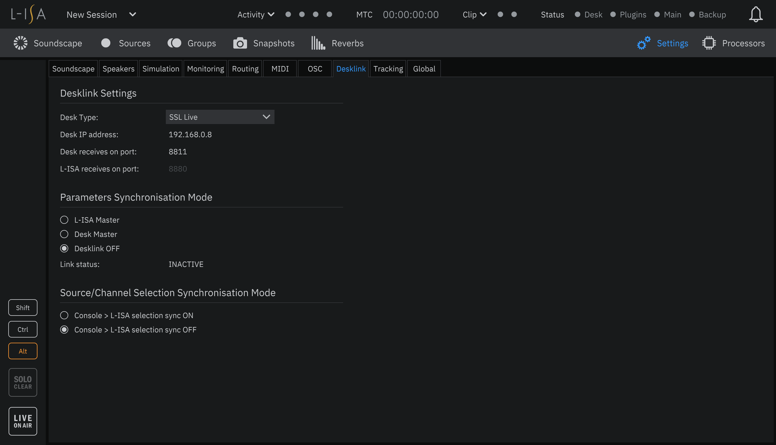
Enter the Desk IP Address into the field provided. This can be found and set in the console's Network options tab (MENU > Setup > Network). Note that each IP address on the network must be unique.
Choose a port number with which to communicate with the SSL Live console. The suggested port number is 8811. Double-click on the Desk receives on port field in the L-ISA DeskLink Settings page and enter the port number.
Console Setup
Navigate to the console's External Control options tab (MENU > Setup > Options). Tap L-ISA in the device list in the OSC SETTINGS section of the page.
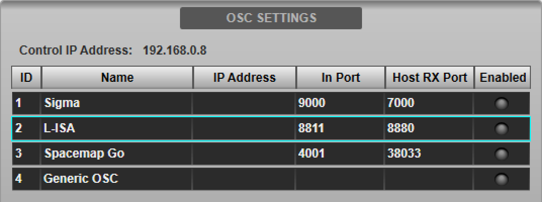
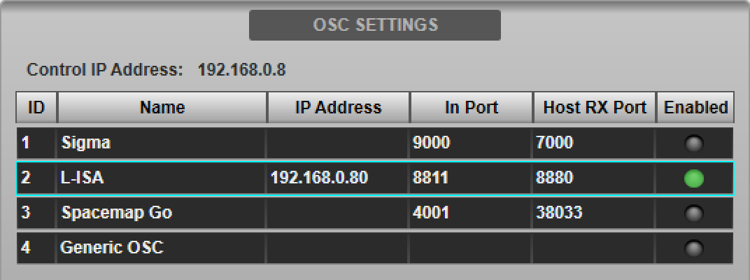
Type in the IP Address of the computer running the L-ISA Controller software in the Host IP Address field provided in the DEVICE CONFIGURATION section below.
Enter the same port number chosen in the L-ISA Setup section above into the Incoming Port field provided. The Name and Host RX Port fields are read-only and for information only.

The IP address entered will be stored in the showfile. Note that each IP address on the network must be unique. The console's IP address is also displayed in this page for reference.
The console's IP address must be in the same subnet as (but not identical to) the IP address of the L-ISA Controller computer and can be changed in the Network options tab (MENU > Setup > Options > Network tab; see Network Options for more details).
Press the Enable Control button to enable control of L-ISA from the console. The Enabled indicator in the device list will light green. Multiple devices can be enabled simultaneously.
Path Assignment
L-ISA control can be enabled on any of the console's mono or stereo Channels or Stems (excluding Dry Channels and Dry Stems).
Navigate to the External Control Detail View page and select L-ISA from the Select Device menu. Enable DeskLink to synchronise L-ISA Controller parameters with the selected console path.
Note that a connection between L-ISA Controller and the console has not yet been established (see below for instructions), so parameter changes will not yet be synchronised between the two systems.
Path Link can be used to assign and enable L-ISA control to multiple paths simultaneously. The selected External Control device and DeskLink enabled state will be stored in the showfile.
Notes:In order for console Channel numbers to be reported correctly to L-ISA, the console must be set to Default channel numbering in the Console Configuration page.
L-ISA supports mono and stereo formatted sources. The console path formats must match the L-ISA sources being associated with them.
L-ISA Controller will only communicate via DeskLink with console Channels 1-256 and Stems 1-64. Console paths can be moved to lower numbered slots using the Console Configuration page.
Audio Routing
The console must be connected to the L-ISA Processor via MADI. Up to three MADI streams may be used for routing up to 96 channels of audio from the console to L-ISA. Add up to three Generic MADI devices to the console's I/O configuration page (see MADI Configuration for details) and connect the corresponding physical MADI ports to the L-ISA processor.
Ensure that the console and L-ISA Processor sample rates match. 96 kHz (recommended) and 48 kHz operation is supported by the console. Refer to Clocking & Sync for details.
Route the Channel/Stem outputs to the configured MADI ports. Please refer to the Routing section for further information.
Note: It is recommended that the Channel/Stem outputs are routed directly to the console's MADI ports and that Channel direct outs are set to Post All processing (please see System Options for further details).Establishing a Connection Between the Console and L-ISA Controller
There are two initialisation options in the L-ISA Controller software, listed under the Parameters Synchronisation Mode section:
- L-ISA Master : Source parameters are sent from L-ISA Controller to all L-ISA enabled paths on the console.
- Desk Master : Source parameters are sent from all L-ISA enabled paths on the console to L-ISA Controller.
The synchronisation mode will depend on workflow; if all source parameter values are stored in the console showfile/scenes then use Desk Master to push those stored settings to L-ISA Controller. However, if source position data is stored in the L-ISA Controller session/snapshots then use the L-ISA Master option to push settings to the console.
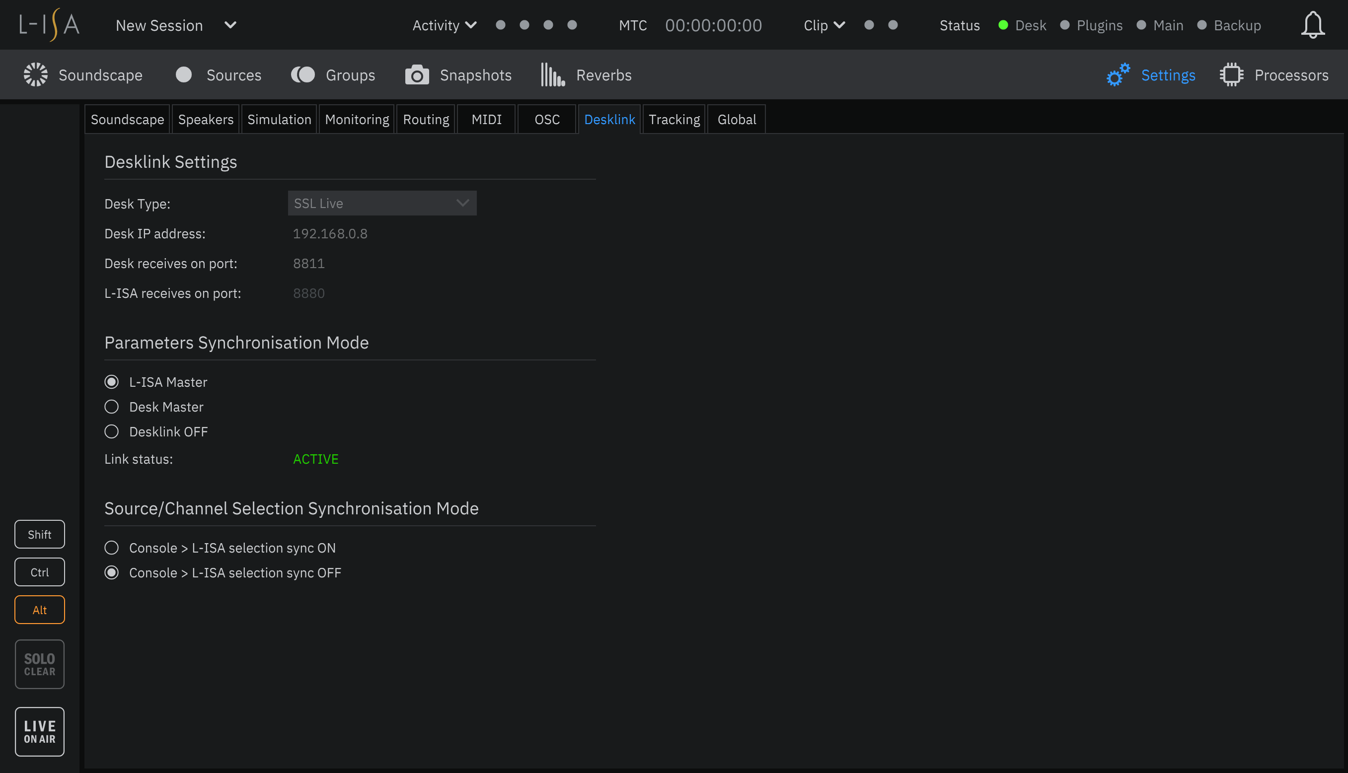
Once L-ISA Control has been enabled on the console and DeskLink has been enabled in L-ISA Controller in either L-ISA Master or Desk Master synchronisation mode, the Link Status in the L-ISA DeskLink Settings page should read ACTIVE and the Desk status indicator in the top right corner of the L-ISA Controller software should light orange or green.
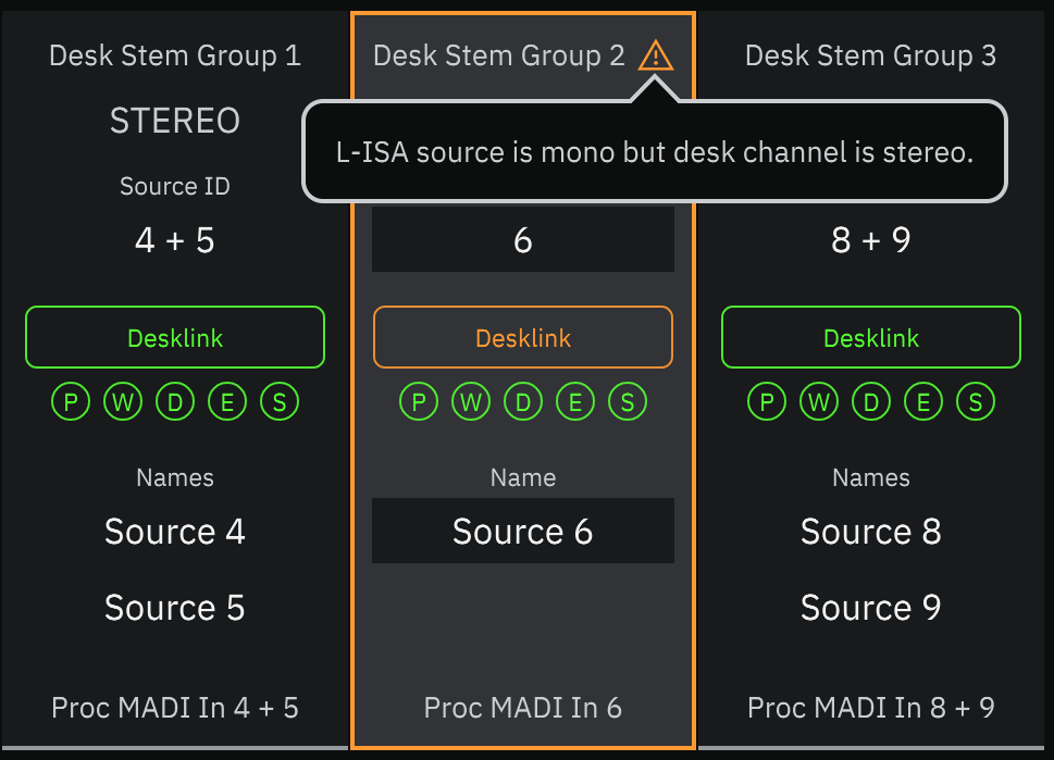
If the Desk indicator lights green, all L-ISA sources have been successfully assigned to console Channels and Stems (see above for assigning control to console paths). However, if the indicator lights orange, some further steps must be taken to allocate L-ISA sources to console paths in the correct configuration. Click on the notification icon in L-ISA Controller to view the error type.
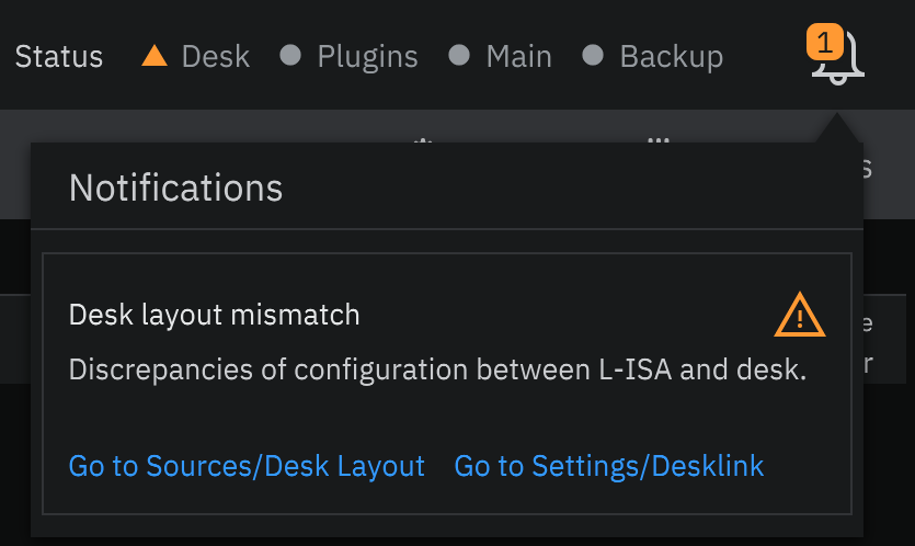
To associate console paths with L-ISA sources, navigate to the Desk Layout tab in L-ISA Controller (Sources > Desk Layout tab).
Any mismatch in configuration (e.g. a mono L-ISA source assigned to a stereo console Channel) will be marked with an orange warning triangle
 in the L-ISA Desk Layout tab; click on these for more information.
Available Controls
When L-ISA DeskLink is enabled on a Channel or Stem, the path's External Control Detail View page will show the L-ISA control interface. This provides control over the following parameters for the associated L-ISA source:
- Pan
- Width
- Distance
- Elevation
- Aux Send (note this is unrelated to any send levels to console Aux buses)
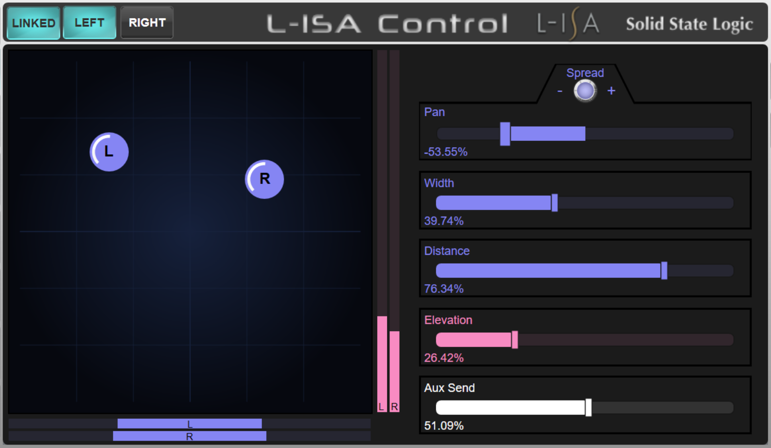
Stereo paths contain some additional features:
- Two sets of the above controls; one for each source in the stereo pair. Accessed using the LEFT and RIGHT buttons above the 2D panning interface
- Link mode, enabled using the LINKED button, allows both sources to be adjusted with the left controls (right controls are disabled)
- Pan Spread encoder to increase/decrease the Pan position between the two sources (up to the extents of the L-ISA Soundscape space). Only available when Link mode is enabled.
Control of L-ISA parameters for the selected path are available on the Quick Control encoders beneath the main screen when Follow Detail mode is enabled. Refer to the Detail View section for further details on the use of Quick Controls.
All of the Channel's/Stem's regular processing and bus controls remain available and function as normal.
L-ISA parameters can be automated in the same way as other path parameters; use the External Control column in the Automation Filters pages to adjust the store and recall scope.
Configuring the L-ISA Master Level Control
Create one OSC Path for the L-ISA Master level control in the Console Configuration page (MENU > Setup > Console Configuration). Refer to the Console Configuration section for further details on using this page.
Place the OSC Path on the console surface using the Layer Manager to assign it to a Fader Tile layer/bank. OSC Paths may also be assigned to the console's Master Tile FOCUS and MAIN faders; refer to the Master Tile section for further instructions.
Navigate to the OSC Path in the Channel View and double-tap the Eyeconix area at the bottom of the screen to open the Name/Eyeconix Detail View page. Name/colour the OSC Path as desired.
Navigate to the External Control Detail View page and select L-ISA from the Select Device menu.
The OSC Path's fader will synchronise to L-ISA Controller's Master level position and can now be used to adjust it.
Note that, like other path types, the OSC Path's fader position can be stored in console automation, but its value will always sync from L-ISA Controller when first connected, even if the L-ISA Controller Synchronisation Mode is set to Desk Master. Care should be taken if automating the fader position as it can cause large changes in level.
Introduction
SSL and Meyer Sound have worked in partnership to provide integrated control of Spacemap Go immersive loudspeaker systems from the console interface. Spacemap sources can be associated with console Channels or Stems, with full control of XY Pan, Crossfade, Spread and Trajectory transport controls for each source available from the console.
Note: This feature is only available when running SSL Live console software version 5.0 and above, Meyer Sound GALAXY firmware version 2.4.2 and above, Meyer Sound Compass version 4.9.2 and above and Meyer Sound Spacemap Go version 1.2.0 and above.Meyer GALAXY and Spacemap Go Setup
Refer to the following references to configure your Meyer Sound system:
- Configure GALAXY Processors: spacemap-go-help.meyersound.com/configure-galaxy
- Spacemap Go Quick Start: spacemap-go-help.meyersound.com/quick-start
From the Spacemap Go app, navigate to the Settings page and select the External Device Connection section on the left. Scroll to the Console section on the right and enter the console's IP address into the External Device (Client) IPv4 Address field. This can be found and set in the console's Network options tab (MENU > Setup > Network). Note that each IP address on the network must be unique.
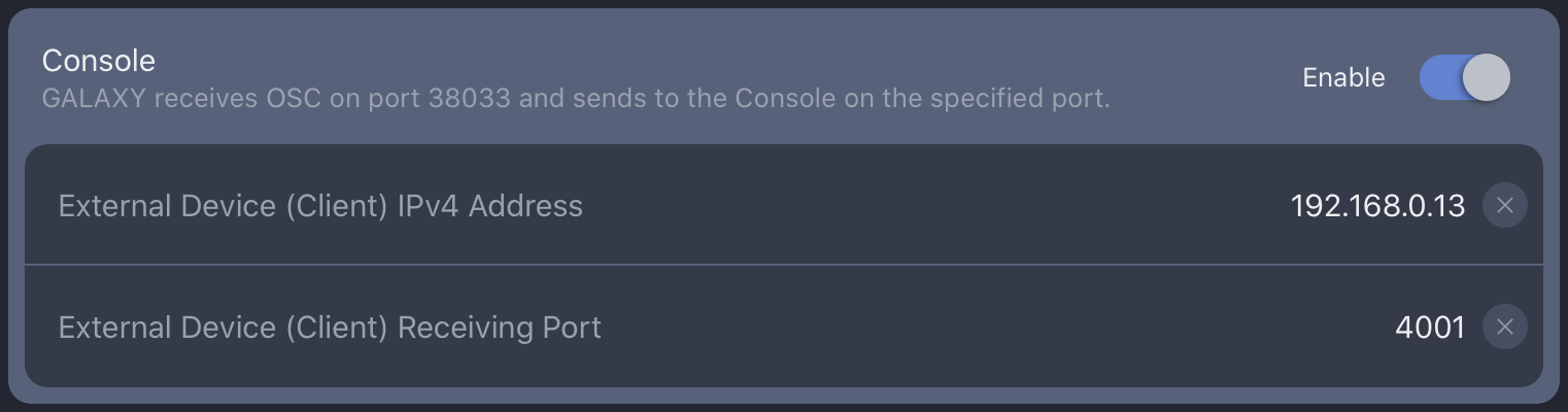
Choose a port number with which to communicate with the SSL Live console. The suggested port number is 4001. Set this in the External Device (Client) Receiving Port field.
Console Setup
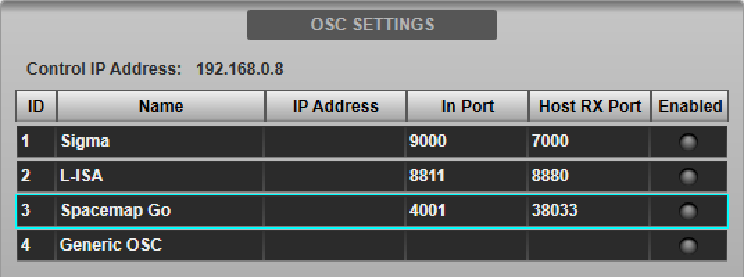
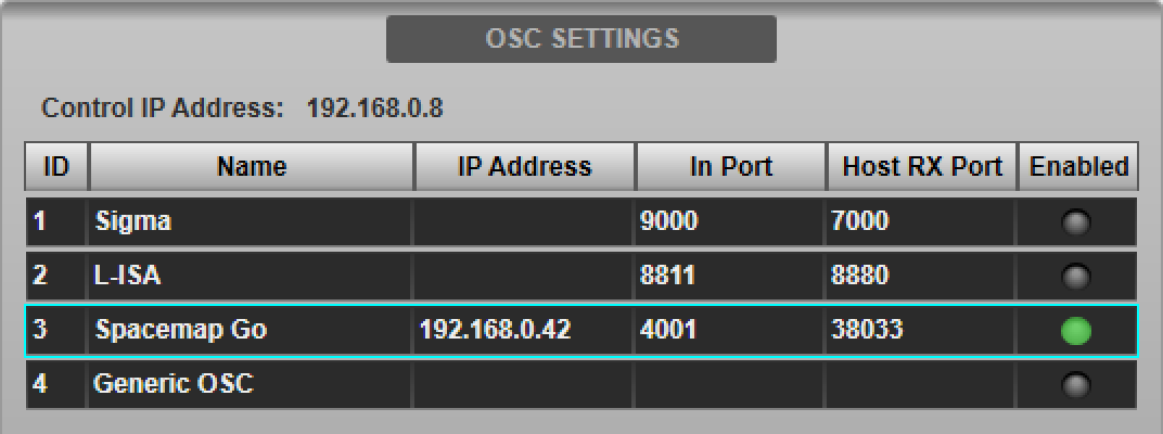
Navigate to the console's External Control options tab (MENU > Setup > Options). Tap Spacemap Go in the device list in the OSC SETTINGS section of the page.
Type in the IP Address of the computer running the Meyer Compass software in the Host IP Address field provided in the DEVICE CONFIGURATION section below.
Enter the same port number chosen in the Spacemap Go Setup section above into the Incoming Port field provided. The Name and Host RX Port fields are read-only and for information only.

The IP address entered will be stored in the showfile. Note that each IP address on the network must be unique. The console's IP address is also displayed in this page for reference.
The console's IP address must be in the same subnet as (but not identical to) the IP addresses of the devices running Compass and Spacemap Go software, and can be changed in the Network options tab (MENU > Setup > Options > Network tab; see Network Options for more details).
Press the Enable Control button to enable control of Spacemap Go from the console. The Enabled indicator in the device list will light green. Multiple devices can be enabled simultaneously.
Path Assignment
Control of Spacemap Go channels can be enabled on any of the console's Channel or Stem paths (excluding Dry Channels and Dry Stems).
Navigate to the External Control Detail View page and select Spacemap Go from the Select Device menu.
Path Link can be used to assign and enable Spacemap Go control to multiple paths simultaneously. The selected External Control device will be stored in the showfile.
Audio Routing
Ensure that the console and Meyer GALAXY Processor sample rates match. 96 kHz (recommended) and 48 kHz operation is supported by the console. Refer to Clocking & Sync for details.
Meyer GALAXY Processors can support analogue, AES3 and AVB inputs. Route the console's Channel/Stem outputs to the required ports for connection to the Meyer Processor. Please refer to the Routing section for further information.
Note: It is recommended that the Channel/Stem direct outputs are used to route to the Meyer system and set to Post All processing (please see System Options for further details).Available Controls
When Meyer Sound Spacemap Go is enabled on a Channel or Stem, the path's External Control Detail View page will show the Spacemap Go control interface. This provides control over the following parameters for the associated Spacemap Go channel:
- X Y Pan
- Crossfade
- Spread
- Trajectory Rate
- Trajectory Transport Controls
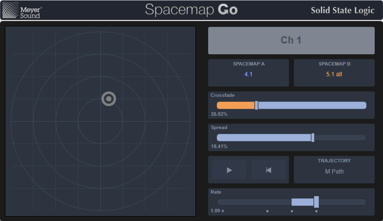
Note that the Spacemap Go iPad app takes control precedence; the console controls will be temporarily disabled while parameters are adjusted in the Spacemap Go app.
All of the Channel's/Stem's regular processing and bus controls remain available and function as normal.
Spacemap Go parameters can be automated in the same way as other path parameters; use the External Control column in the Automation Filters pages to adjust the store and recall scope.
However, it is recommended by SSL and Meyer Sound that console automation of External Control parameters is disabled for paths using Spacemap Go and that Spacemap Go parameters are instead automated in the Meyer Sound automation system.
Configuring the Spacemap Go Master Level Control
Create one OSC Path for the Spacemap Go Mix Master level control in the Console Configuration page (MENU > Setup > Console Configuration). Refer to the Console Configuration section for further details on using this page.
Place the OSC Path on the console surface using the Layer Manager to assign it to a Fader Tile layer/bank. OSC Paths may also be assigned to the console's Master Tile FOCUS and MAIN faders; refer to the Master Tile section for further instructions.
Navigate to the OSC Path in the Channel View and double-tap the Eyeconix area at the bottom of the screen to open the Name/Eyeconix Detail View page. Name/colour the OSC Path as desired (e.g. SMG Master).
Navigate to the External Control Detail View page and select Spacemap Go from the Select Device menu.
The OSC Path's fader will synchronise to the Spacemap Go Mix Master level position and can now be used to adjust it.
Note that, like other path types, the OSC Path's fader position can be stored in console automation, but as with the per-path Spacemap Go controls described above, it is recommended that External Control parameters are disabled in console automation. Care should be taken if automating the fader position as it can cause large changes in level.
Automating Spacemap Go parameters
In order to prevent possible data conflicts, Spacemap Go parameters should be stored in only one automation system; either in Spacemap Go (recommended) or in the console.
To disable recall from the console's automation system, navigate to the Automation page (MENU > Automation) and select the Global Recall Filters page (refer to the Automation Filters section for details). Navigate to the paths that have Spacemap Go control enabled and ensure the External Control column is turned off for these paths.
Note: This will only disable recall of the External Control parameters. To disable storing these parameters, turn off the External Control column in the Global Store Filters page as well.Using a Generic OSC Path to Trigger Spacemap Go Snapshots
To trigger Spacemap Go snapshots in sync with firing console scenes, a Generic OSC device assigned to an OSC path can be used (see below for setup details).
Configure the Generic OSC device with the same IP address and port numbers as the Spacemap Go device configured above.
Configure one of the Generic OSC Faders with an OSC Address of /Console/recall/system. Spacemap Go system snapshots can be given an External Recall ID of between 900 and 3000. Set the Fader's Min and Max fields to cover the number of snapshots required. Bear in mind that the Fader is represented in percent, so a range (Min and Max) of 900 to 1000 would mean that a 1 % change in Fader position equates to increasing the External Recall ID by 1 (starting at 900). For example, a Fader value of 42 % would equal snapshot #942 (900+42).
Tip: Generic OSC Fader 1 is mapped to the physical fader when assigned to an OSC Path. It is therefore recommended that another fader number is used, so as to prevent accidental physical fader moves causing a snapshot change.Create a new OSC Path in the Console Configuration page (MENU > Setup > Console Configuration). Refer to the Console Configuration section for further details on using this page.
Ensure that the OSC Path's External Control parameters are set to store and recall in the console's automation scenes. Refer to the Automation Filters section for details.
Place the new OSC Path on the console surface for ease of access using the Layer Manager (or use the Layers button in the Channel View sidebar to gain access).
Navigate to the OSC Path in the Channel View and double-tap the Eyeconix area at the bottom of the screen to open the Name/Eyeconix Detail View page. Name/colour the OSC Path as desired (e.g. SMG Snapshot).
Navigate to the External Control Detail View page and select Generic OSC from the Select Device menu.
In each console scene you wish to trigger a Spacemap Go snapshot change, change the OSC Fader position to match the required Spacemap Go External Recall ID number, bearing in mind the offset and range (Min and Max) of values entered above. Remember to Store this value in the console's automation system so it is recalled when the scene is fired.
Tip: Tap on the OSC Fader to select it then double-tap in the text field in the lower right corner of the Detail View to bring up a keyboard for entering a specific value. Refer to the Detail View section for further details.When a scene is fired that contains a new value for the OSC Fader in the Generic OSC Path, an OSC message will now be sent to Spacemap Go prompting a snapshot change to coincide with the console automation scene change.
Introduction
SSL and d&b have collaborated to bring integrated control allowing users to position objects within the d&b Soundscape immersive loudspeaker system directly from SSL Live consoles. Up to 64 objects can be configured per DS100 processing engine in Soundscape, all of which can be controlled from the console. Objects can be controlled from console input Channels or Stem group buses with full control of XY Pan, Spread, En-Space Send, Delay Mode and Mapping Area from the channel detail view.
"Powered by the DS100 Signal Engine, a revolutionary audio system processor based on a powerful Dante enabled signal matrix, d&b Soundscape provides unparalleled creativity through its two software modules En-Scene and En-Space."
The d&b DS100 processor includes Dante IO (64ch at both 48kHz and 96kHz). Audio connectivity with the console is best achieved via one of SSL Live console's Dante options. Control communication is across the console's Connectivity network directly with the DS100.
Note: This feature is only available when running SSL Live console software version 5.2 and above,d&b Soundscape Setup
Within the console Setup menus, navigate to Options > External Control. Select the d& soundscape entry from the OSC settings list to show the details on the DEVICE CONFIGURATION pane.
- Enable Control - Toggles the OSC communication for d&b soundscape on and off.
- Host IP Address - Requires the IP address of the DS100 device. (Default 50010)
- Incoming Port - Not required for direct connection to the DS100, to be used with d&b software bridge app (Remote Protocol Bridge).
- Host RX Port - Requires setting to the inbound port on the DS100 for direct communication.
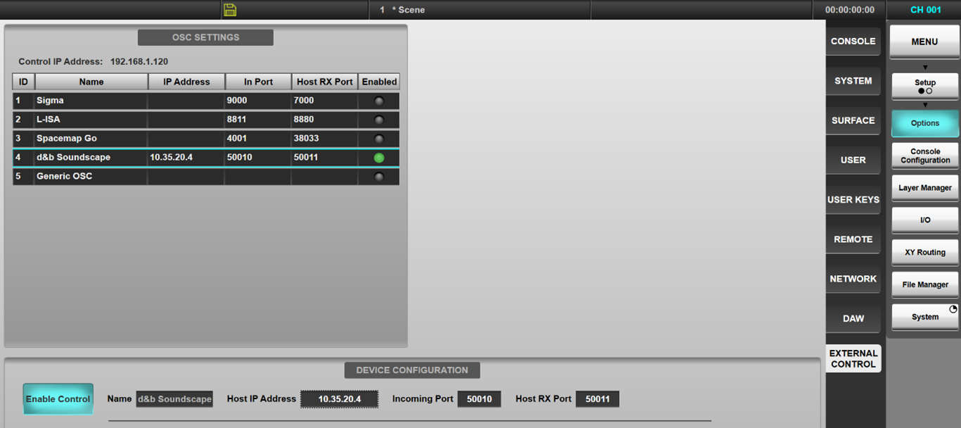
The Host IP address entered will be stored in the showfile. Note that each IP address on the network must be unique. The console's IP address is also displayed in this page for reference. The console's IP address must be in the same subnet as - but not identical to - the IP addresses of the DS100, and can be changed in the Options > Network tab.
Audio Path Mapping
Any console Channel or Stem (excluding Dry variants) may have Soundscape control enabled on it.
Navigate to the External Control Detail View page and select d&b Soundscape from the Select Device menu. The Control Path Num Offset field allows an offset to be added to the path number when transmitted to the OSC device. For example, if 48 mono Channels and 8 Stems are being used, the Channels would use an offset of 0 (d&b source IDs 1 to 48) while all Stems would use an offset of 48 (d&b source IDs 49-64).
Path Link can be used to assign and enable d&b Soundscape control to multiple paths simultaneously. The selected External Control device per path will be stored in the showfile.
Audio Routing
The DS100 has a Dante interface; audio connections to/from the console will be via the onboard console Dante expander, or the high-capacity BLII/X-Light Bridge interfaces. Audio connections can be via Virtual Tie Lines (managed with Dante controller), or Dynamic Dante (Dual Domain) Routes made using the console software. For Dynamic Dante Routing from console the DS100 must be added to the Configured Devices list in the Dante configuration page. Once configured any console routing UIs can be used to patch path inputs and outputs to and from the DS100; these Dynamic Dante routes will be stored and recalled with the console showfiles.
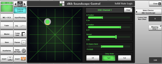
d& Soundscape Controls
Within the console paths detail view, the d& controls are displayed on a UI designed for the touch screen but can also be controlled from the encoders in follow detail mode. The following parameters are controllable:
- X and Y relative to coordinate mapping area (controlled using the 2D position graphic, the two sliders, or two encoders in follow detail mode).
- Spread (controlled using pinch on the position graphic, the dedicated slider, or encoder in follow detail mode).
- En-Space Send (controlled using pinch on the position graphic, the dedicated slider, or encoder in follow detail mode).
- Delay Mode (toggled between Off, Tight & Full) with the onscreen buttons or hardware switch in follow detail mode).
- Mapping Area (press and hold to choose area 1 to 4 - see d& Soundscape for details).
Controls across multiple channels can be Path Linked and controlled as a set, in the same way console parameters can be.
Soundscape parameters can be scene automated in the same way as other path parameters; use the External Control column in the Automation Filters pages to adjust the store and recall scope.
Advanced Use with d&b Remote Protocol Bridge (RPB)
For workflows involving control from multiple user interfaces - for example the console and R1 - bidirectional communication with the console is required. The DS100 does not directly communicate using OSC, therefore the d&b Remote Protocol Bridge app is required.
The d&b Remote Protocol Bridge will also allow support for 2x DS100s. These can be configured as units in parallel, for redundancy, or as two individual units providing up to 128 sound objects within the Soundscape System.
Please speak to your local SSL Support team for use cases including Remote Protocol Bridge.
Introduction
The console is able to control many devices that support the OSC (Open Sound Control) standard via the UDP network protocol.
Please refer to individual device manuals to determine if they support remote control via OSC and for device-specific setup instructions.
To control third-party devices from the console surface via OSC, the following pieces of information are required
- IP address of the device to control
- Console incoming port number (i.e. the port to which the device will send OSC packets)
- Device receiving port number (i.e. the port to which the console should send OSC packets)
- OSC method addresses and data types for the parameters to be controlled
Refer to the Open Sound Control website (www.opensoundcontrol.org) for further details on the OSC protocol.
Console Setup
Navigate to the console's External Control options tab (MENU > Setup > Options). Tap Generic OSC in the device list in the OSC SETTINGS section of the page.
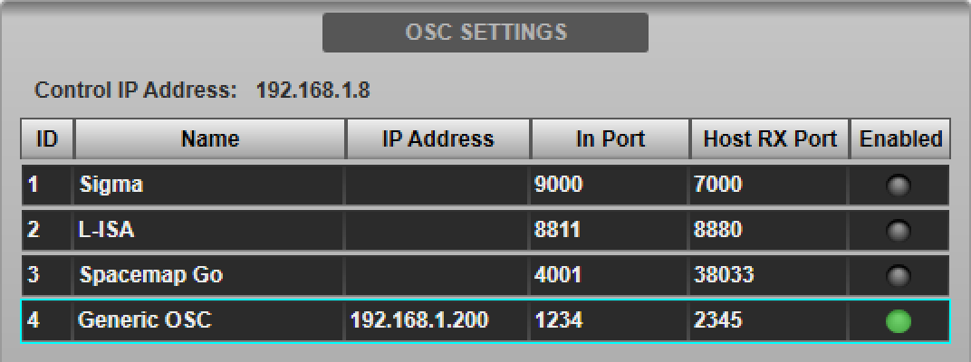
Enter the IP Address and port numbers of the device in the Host IP Address, Incoming Port and Host RX Port fields provided in the DEVICE CONFIGURATION section below.

Some third-party devices require the console to respond to OSC messages by echoing back the value received. If this is the case then ensure the Enable Parameter Echo button is engaged. Please consult the device's manual for details. If in doubt, start with Enable Parameter Echo off and enable only if all other settings are correct but communication with the device is still not successful.
The settings entered will be stored in the showfile. Note that each IP address on the network must be unique. The console's IP address is also displayed in this page for reference.
The console's IP address must be in the same subnet as (but not identical to) the IP address of the OSC device and can be changed in the Network options tab (MENU > Setup > Options > Network tab; see Network Options for more details).
Defining OSC Methods
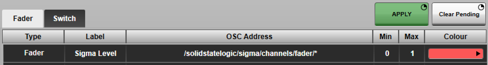
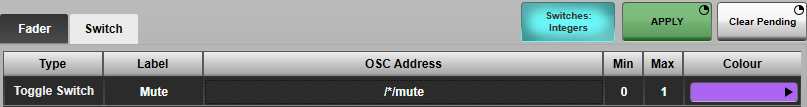
Up to eight Fader (i.e. continuously variable) and eight Switch parameters per third-party device channel may be defined for control by the console. These are defined in the relevant tabs in the DEVICE CONFIGURATION section.
For each parameter, enter the following information:
- Label : The text displayed beside the control in the console interface. A * character will be substituted with the originating console path number (including the Path Num Offset; see Path Assignment section below). e.g. Entering "Mute ch *" will display "Mute ch 1" on console path number 1, "Mute ch 2" on path number 2 etc.
- OSC Address : The address of the OSC method to control. The console only handles float data types. A * character will be substituted with the originating console path number (including the Path Num Offset; see Path Assignment section below). e.g. Entering "/solidstatelogic/sigma/channels/fader/*" will communicate with an SSL Sigma's fader 1 OSC method from console path number 1, fader 2 from path 2 etc.
-
Min and Max values
- Faders : Linearly interpolates between Min and Max.
- Switches : Off = Min, On = Max. Typically 0 and 1 respectively; refer to the device manual.
- Colour : The colour in which to display the control on the console interface.
The Switch tab has an extra option to set the data type to Integer. This restricts the switches to only respond to, and send, OSC messages with integer arguments.
Press & hold the Apply button to store the parameters.
Use the Clear Pending button to reset the parameter list to the currently applied state.
Press the Enable Control button to enable control of OSC device from the console. The Enabled indicator in the device list will light green. Multiple devices can be enabled simultaneously.
Creating Console OSC Paths
Control of Generic OSC devices is accessible from console audio paths as well as dedicated OSC paths with no console audio processing associated to them. Which to choose will depend on whether the third-party device interacts directly with console audio paths (e.g. an outboard effects processor inserted over certain channels), or is unrelated to specific audio paths (e.g. a show control system for triggering lighting cues).
Control is possible from both audio and OSC paths simultaneously, but care must be taken that they address different channels on the third-party device; see the Path Assignment section below for further details.
If dedicated OSC Paths are required, create these in the Console Configuration page (MENU > Setup > Console Configuration). Refer to the Console Configuration section for further details on using this page.
Path Assignment
Place the audio/OSC Paths on the surface using the Layer Manager. OSC may be placed in banks as desired, just like any other path type. Depending on the workflow desired, a dedicated bank could be created, or OSC Paths can be interspersed with other console paths.
Navigate to the paths in the Channel View and double-tap the Eyeconix area at the bottom of the screen to open the Name/Eyeconix Detail View page. Name/colour the paths as desired.
Navigate to the External Control Detail View page and select Generic OSC from the Select Device menu.
When communicating with the third-party device, the displayed path number will be used as the device channel number to control. The Control Path Num Offset field in the External Control Detail View page can be used to apply an offset to the path number. E.g. if console OSC Path 8 is to control device channel 4, an offset of -4 must be entered. Path Link can be used to assign Generic OSC and apply offsets to multiple OSC Paths simultaneously. The selected device and offset per path will be stored in the showfile.
Note: Care should be taken that the same device channel is not accessed via more than one console path, either by assigning to different path types (e.g. OSC path and Channel) and/or through use of the Control Path Num Offset field.Parameters within OSC Paths can be automated in the same way as other path types; use the Automation Filters to adjust the store and recall scope.
Available Controls
The parameters configured in the Generic OSC device setup (up to eight faders and up to eight switches) can be accessed from the External Control Detail View page of any path configured to control the Generic OSC device.
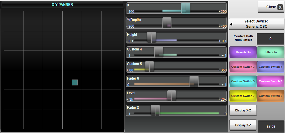
The graphical panner on the left represents the first three configured fader parameters - notated as X, Y and Z. This allows a graphical representation of 3D/Surround panning in many third-party, OSC-enabled, immersive audio processors.
The dimensions shown on the graphical panner can be selected via the Display X-Z and Display Y-Z buttons in the bottom right.
If assigned to an OSC path, the path's Fader will control the first Fader parameter configured in the device. The path's Mute and Solo switches will control the first and second switch parameters respectively. These can be accessed from the Fader Tile hardware and various Fader sections of the GUI (Detail View, Channel View etc.)
KLANG Immersive Panning
Please see the KLANG Integration page for information on how to set up a KLANG system with SSL Live.
