
I/O Setup: Local/MADI Configuration
Local/MADI Configuration is where you define I/O names and settings for local and MADI connections. These settings are saved with the showfile.
To open this menu go to Menu > Setup > I/O then tap Local/MADI Configuration.
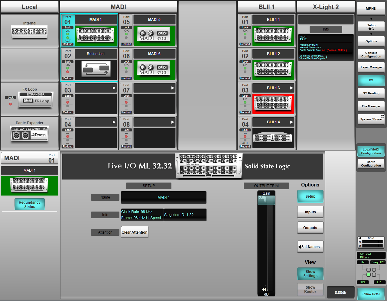 Note: The above screenshot is from the L650. Other SSL Live console models have differing amounts of I/O but the principles are the same.
Each column represents a different I/O card type:
- Local shows the Internal I/O, FX Loop MADI fibre and optional Dante module.
- MADI shows the BNC/SC fibre MADI ports on the rear of the console. These are arranged in groups of four or eight ports, identified by a letter (A, B or C) in the column title and matching the console's rear panel labelling.
- BLII or X-Light represent the optional Blacklight II/X-Light ports to connect to Blacklight II to MADI Concentrators, Net I/O BLII Bridges or X-Light Bridges. Up to two BLII ports may be fitted, identified by a 1 or 2 in the column heading and the console's rear panel labelling.
Configuring BLII/X-Light Ports
Blacklight II (BLII) and X-Light are SSL proprietary high bandwidth digital audio transport protocols. BLII carries 256 audio channels @ 96 kHz or 48 kHz, bi-directionally down a single or redundant pair of Neutrik OpticalCON Duo multimode fibres (singlemode fibre option also available by special order). Control data for MADI stageboxes is also carried over BLII.
X-Light carries 256 audio channels @ 96 kHz or 48 kHz, bi-directionally down a single or redundant pair of Neutrik OpticalCON Quad multimode fibres. The console's Dante control signals and local Dante Expander audio is also transported over X-Light.
To use the BLII/X-Light port(s) on SSL Live consoles for MADI devices and SSL MADI Stageboxes, a BLII to MADI Concentrator must be used. The BLII to MADI Concentrator box located at the stage is then used to distribute standard coaxial MADI to the analogue and AES/EBU Stageboxes, a second SSL Live console or other MADI devices.
To use the BLII/X-Light port(s) on SSL Live consoles for Dante devices and SSL Net I/O Dante Stageboxes in non-ruggedised and fixed install applications, a Net I/O BLII Bridge is recommended. The BLII Bridge located with the console is used to expand the console's Dante I/O count.
To use the BLII/X-Light port(s) on SSL Live consoles for Dante devices and SSL Net I/O Dante Stageboxes in ruggedised/touring applications, a Net I/O X-Light Bridge is recommended. The X-Light Bridge located on stage is used to expand the console's Dante I/O count.
To configure a BLII/X-Light port, on the console go to MENU > Setup > I/O > Local/MADI Configuration.
If there are no devices configured in the relevant BLII/X-Light port when the BLII to MADI Concentrator/BLII Bridge/X-Light Bridge is connected, the connected device will be automatically detected and configured.
If there are already devices configured in the relevant BLII/X-Light port, the port will need to be manually configured.
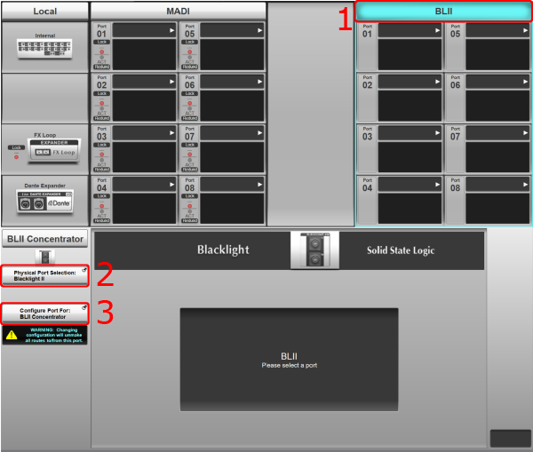
To configure the BLII/X-Light port:
- Tap on the relevant port column heading to view settings for the port.
- Press & hold Physical Port Selection: in the Detail View of the port and select Blacklight II (for BLII Concentrator or Net I/O BLII Bridge) or X-Light (for X-Light Bridge). Note that for L450, L550 and L650, X-Light is always connected to the second BLII/X-Light port (the right-most column in the I/O page).
- Press & hold Configure Port For: and select the desired device if required.
 Note: L100, L200 and L350 consoles fitted with both BLII and X-Light ports can only utilise one of these port types at a time.
Caution:
Take care when reconfiguring the BLII/X-Light ports as routes will be unmade.
- If reconfiguring the BLII port from BLII-MADI Concentrator to BLII Bridge, all existing routes between the console and devices connected via the BLII-MADI Concentrator will be unmade.
- If reconfiguring the BLII port from BLII Bridge to BLII-MADI Concentrator, ALL Dante dual domain routes will be unmade regardless of whether they route through the BLII Bridge or the Dante Expander Module. Virtual Tie Line routes made to the Dante Expander Module will remain.
BLII/X-Light port configuration is stored in showfiles.
If using a BLII to MADI Concentrator, this device is now configured and ready for use.
If using a Net I/O BLII Bridge or X-Light Bridge please see Working with BLII & X-Light Bridges.
MADI and MADI over BLII
The following instructions apply to devices connected over MADI or via a BLII to MADI Concentrator.
Each port will auto-detect SSL Live stageboxes. MADI and Blacklight ports provide exactly the same configuration options.
Note: Some MADI and BLII columns can be scrolled by swiping the screen up or down.You may also pre-configure I/O before it is connected (with SOLSA offline software for example):
Touch the dark grey box in the top of the port and select the required device type.
Note: To change to a different device, you will need to confirm the change from the detail pane beneath the list of MADI and BLII ports.If the defined device doesn't match what the port detects, the box's background will go red; check your connections or change the device type manually. Confirm the device you wish to use from the Detail pane beneath the list of MADI and BLII ports.
Note: If you change to a different device once you have based further settings on the original configuration, your settings may no longer work.The device options are as follows:
- None - nothing connected
- Generic MADI - any third party I/O
- ML 32.32 - 32 analogue I/O
- ML I.32 - 32 analogue inputs only
- ML O.32 - 32 analogue outputs only
- D 32.32 - 16 AES I/O pairs
- Live Recorder - connect a MADI multitrack recorder for rehearsal mode - This option was removed in V5.2 and Generic MADI should be used instead.
The two LEDs beneath each port's number indicate the lock and redundancy status of the port:
If the upper LED is green, the port's I/O unit is correctly locked; if it is red, it isn't locked.
If the lower light is lit, it means that it is part of a redundant pair (described below).
Note: If using a 16-port Blacklight MADI concentrator, there will be four lights; one pair for each redundant hardware connection.Redundancy
Each MADI port can function as part of a redundant pair. Ports are always in Odd/Even pairs – Port 1 will always pair with Port 2 for example.
To define a redundant pair:
Touch one of the Ports' box to open its detail dialogue.
Touch the Redundancy Status button to its left. It will light to indicate that the Port is now part of a redundant pair and a cyan box will appear around both Ports to indicate they are linked. The lower status lights of the two ports indicate which is the currently active port; green for the active port and red for the backup port.
The first port's settings will now be applied to the pair of ports.
Notes:The fibre-optic connections from the console to any Blacklight II.MADI Concentrator always have redundancy available – simply plug up the second fibre-optic connection. Redundancy here refers to the MADI redundancy from the console or Blacklight II Concentrator box to further devices.
If using a 16-port Blacklight II.MADI Concentrator, each port always has redundancy available so there is no need to turn on the Redundancy Status button.
When a 16-port Blacklight II.MADI Concentrator is connected, each port will change to have four status lights. The left pair corresponds to the lower row of MADI connectors; the right pair corresponds to the upper row of MADI connectors. As with the 8-port version, the upper lights indicate the MADI lock status (green = locked, red = not locked) and the lower lights indicate which of the redundant ports is active (green = active, red = backup).
MADI Stagebox Port Configuration
Touching on the box for a port or connection brings up that port's settings in the Detail dialogue in the lower half of the page.
For stageboxes, the page buttons on the right (Setup, Inputs and Outputs, or AES I/O for the local AES I/O) allow you to page through the port's settings:
Setup:
Double-tapping the black name box brings up a keyboard on which you can enter a name for the port.
The Set Names button can be used to select a preset name for the device. Note that this does not affect the names of individual inputs and outputs; only the device name itself.
The Output Trim slider introduces a global level trim on all analogue line outputs from the stagebox, relative to the console's Operating Level (set in Menu > Setup > System / Power > System tab). Note this does not affect the optional mic split outputs (if fitted), which are always at mic level.
The Clear Attention button clears all of the Att lights on the local I/O. The rest of the page displays format and clocking information.
Inputs and Outputs:
Touching the Inputs or Outputs button brings up a display showing all of the individual connections within the stagebox. Each connection's box displays its name and essential settings. Use the Show Settings and Show Routes buttons to toggle the display between showing preamp settings and routing information.
Touching a connection box will display controls on the right of the screen.
To name a connection:
- Touch the connection's box; its number (or name) will appear in the name box in the top-right of the detail display.
- Double-tap the name box and use the keyboard which appears to enter a new name.
- Touching Use Default will return the connection name to its default name.
- Alternatively, press the Set Names button to pick a range of names to apply to all inputs or outputs in the stagebox. Note that using Set Names for inputs does not affect output or stagebox names and vice versa.
To control a preamp (analogue inputs only):
- Touch the connection's box; controls for the selected input will appear to the right of the Detail display.
- Use the Show Gain button to toggle between displaying the analogue gain and other controllable parameters.
- Use the padlock button to unlock the controls for modification.
AES I/O
All AES IO have sample rate converters (SRCs) available, and they are engaged by default.
Touching the AES I/O (Internal) or Inputs/Outputs (D32.32) button brings up a display showing all of the individual AES connections within the unit. Each connection's box displays its name and essential settings. Use the Show Settings and Show Routes buttons to toggle the display between showing SRC settings and routing information.
Touching a connection box will display controls on the right of the screen.
When selecting an AES input you will be presented with a single SRC In button in the top right corner of the detail section. The console supports the input rates listed in the Input Rate column in the table below and will convert the incoming audio to 96 kHz for use within the Live system.
The table below also shows the sample rates available for AES/EBU outputs. There are some additional controls for output connections.
Note: The multiplier controls (x1, x2 and x4) are relative to a base sample rate of 44.1 or 48k, not the operating rate of the console (48 or 96k).Engaging SRC In and setting the output clock to In will clock the AES output from the corresponding AES input, at 1, 2, or 4 times the base rate (44.1 or 48k).
Setting the output clock to Int will use the console as the clock source. This can also be set to x1, x2, or x4 of this base sample rate (48k).
Configuring Other I/O
Detail Dialogues are available for other I/O ports as well:
Internal
The Internal Detail Dialogue provides an ANA OUT Trim slider, which introduces a global level trim on all local analogue outputs, relative to the console's Operating Level (set in Menu > Setup > System / Power > System tab). The Clear Attention button clears all of the Att lights on the local I/O.
In the right side of the window, there are boxes for each local AES connection. Touching these provides access to essential AES settings, as described for AES I/O above.
The remaining I/O detail dialogues simply display essential information about the card or port.
Dante
A Dante Expander Module may also be fitted to the Live console. This adds up to 64 channels of Dante I/O to the console (dependent on sample rate; see below).
Select the Dante Expander Module from the left-most column in the I/O page. You will be presented with options for the Dante Expander in the lower portion of the screen. The Recorder ID buttons are described in the next section: Multitrack Recording & Playback. Select the Free Route button to freely route the Dante I/O within the console routing system.
The number of channels available for routing on the console will vary based on the console and Dante network sample rates. If the Dante network is running at a different sample rate or in a different clock domain to the console, engage the SRC In button. This will sample rate convert incoming and outgoing audio between the console and Dante network. The table below summarises the sample rate combinations available (note the number quoted is for each direction, e.g. 32 = 32 inputs AND 32 outputs):
| Console Sample Rate | Dante Expander Sample Rate | Dante Expander Sample Rate Conversion | Quantity of Dante Inputs and Outputs |
|---|---|---|---|
| 96 kHz | 192 kHz | SRC In | 16 |
| 96 kHz | 96 kHz | SRC Out | 32 |
| 96 kHz | 48 kHz | SRC In | 32 |
| 48 kHz | 192 kHz | SRC In | 16 |
| 48 kHz | 96 kHz | SRC In | 32 |
| 48 kHz | 48 kHz | SRC Out | 64 |
You should not clock the console from the Dante network with the Dante SRC engaged. For more information about clocking to or from a Dante network, please refer to the Clocking the System section.
For more information on setting up Dante, Net I/O Stageboxes or a BLII/X-Light Bridge, please see I/O Setup: Dante.
AES67
AES67 is an interoperability standard for audio over IP networks. The console's Dante interfaces support AES67; this can be enabled from the device's AES67 Config tab in Dante Controller. Once enabled, AES67 flows can be created using Dante Controller for transmitting audio to other compatible devices that support AES67. Please refer to the Audinate Dante Controller manual for information on creating AES67 flows.
Useful Links:
Setting Up DanteNetwork I/O Stageboxes
Installation Guide
Index and Glossary
