
Quick Start Guide
This page is designed to get you up and running quickly.
If you would like to learn more about any of the topics covered, return to the Homepage where each section of the console is described in detail.
Please Note: If using Dante Stageboxes, this Quick Start Guide assumes that the reader has completed Dante Certification Levels 1 & 2 or has equivalent Dante experience. If this is not the case please refer to Setting Up Dante to learn more.1. Turn on the console
On the rear of the console, turn the PSU switches to the "on" position (L100 consoles fitted with dual-redundant power supplies do not have these switches).
Now press the PSU switch on the console's Control Tile or Tablet Tile.
The console will now start.
2. Set the Sample Rate
On the console go to the System page (MENU > Setup > System / Power > System tab).
Press and hold the 96 kHz or 48 kHz button to choose the Sample Rate. Once the button starts flashing, you can let go.
Reboot the console if the sample rate has been changed.
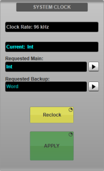
3. Choose a Clock Master
On the console go to MENU > Setup > Options > SYSTEM tab.
In the System Clock section, choose a Main clock master from the available options. Optionally select a Backup clock source.
Press and hold APPLY.
For MADI-based systems, SSL recommends selecting the console as the clock master (choose Int (internal clock) on the screen). The stageboxes and all other MADI devices should slave to the console.
For Dante-based systems, SSL recommends that the console slaves to Dante (choose Dante Expander on the screen) to take advantage of Dante's clock election process.
See Clocking for more information.
4. Load a Template Showfile
Go to MENU > Setup > File Manager > Showfiles tab.
Tap on System Templates to the left.
Choose a template that best fits your system:
- ... over BLII-MADI Concentrator templates refer to systems using MADI stageboxes and a BLII-MADI Concentrator
- ... over MADI templates refer to systems using MADI stageboxes connecting directly to the console (without a BLII-MADI Concentrator)
- ... over Dante - Local Dante Port templates refer to systems using Dante stageboxes with no BLII Bridge
- ... over Dante - BLII Bridge templates refer to systems using Dante stageboxes with a BLII Bridge
- ... over Dante - X-Light Bridge templates refer to systems using Dante stageboxes with an X-Light Bridge
Tap on a template and press and hold Load.
SSL recommends: For the purposes of this Quick Start Guide, please do not load the Blank showfile.The other templates have been configured so that most of the work has already been done for you. The setup process will take much longer using the Blank showfile.
When a template is selected, the Showfile Notes area describes the settings for that showfile. You can refer back to this at any time. Double tap on the Showfile Notes area to edit the notes.
Tap the HD button to the top of the showfile list. Press Save As and type in the name of your showfile. Press OK.
SSL recommends: It is recommended that showfiles are run from the console's internal hard drive, and not from a USB stick. The console saves a backup showfile every minute. In the event of a power loss, when the console is powered back on, the most recent backup showfile will be loaded. Backup showfiles cannot be saved to a USB stick, so this protection is not in place if a showfile is run from a USB stick.5. Connect the Stageboxes
MADI Stageboxes
The following instructions apply to MADI stageboxes with analogue inputs: ML 32.32 & ML i32.
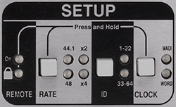
Stagebox Sample Rate & Clocking
On the rear of the stagebox, locate the SETUP section. Check that the Sample Rate listed matches that which you have set the console to. There is no Sample Rate Conversion for MADI connections.
If the Sample Rate does not match, press and hold the RATE and CLOCK buttons until the padlock LED starts to flash.
Press the RATE button repeatedly until the Sample Rate listed matches the sample rate of the console. Please note that 96 kHz is displayed with the 48 and x2 LEDs illuminated.
Press the CLOCK button repeatedly until the MADI LED is illuminated green. The stagebox will now clock from the console. If it is illuminated red, there is an invalid clocking scheme. If this is the case, go over step 3 again to check if anything has been missed.
Ensure that the ID section has the 1-32 LED illuminated (unless daisy-chaining stageboxes at 48 kHz). Press ID button repeatedly until the 1-32 LED is illuminated. (If daisy-chaining stageboxes at 48 kHz please see the Clocking section).
Stagebox Connection
The Blacklight II (BLII) Concentrator allows up to 8 MADI devices to be connected to the console redundantly via a pair of fibre cables.
Connect MADI Port 1 on the rear of the Stagebox to Port 1A on the rear of the Blacklight II Concentrator via BNC.
Connect MADI Port 2 on the Stagebox to Port 1B on the BLII Concentrator via BNC.
Connect BLII A Main on the front of the BLII Concentrator to BLII Port 1a on the rear of the console via a Neutrik OpticalCON DUO connection.
Connect BLII A Backup on the BLII Concentrator to BLII Port 1b on the console via a Neutrik OpticalCON DUO connection.
Please Note: If you do not have a BLII-MADI Concentrator, stageboxes can also be connected directly to the console. To do this simply connect stagebox MADI Ports 1-2 directly to an odd/even pair of MADI ports on the console via BNC.On the console go to MENU > Setup > I/O > Local/MADI Configuration.
To the right of the screen, under the BLII heading(s), the first port should be green with an image of the stagebox. If the background is red or grey, or there is no stagebox image, please see Local/MADI I/O Configuration.
Repeat the above steps for any additional MADI stageboxes.
Routes have now been made from the stagebox to Channel inputs via a 1:1 patch. For Monitor templates, Aux Mix outputs have also been routed. To adjust these routes please see Routing.
Dante Stageboxes
The following instructions apply to Net I/O SB 32.24 stageboxes only. If you are connecting to another Net I/O stagebox please see Network I/O Stageboxes.
Please Note: SSL Live consoles contain 4 network devices for use with Dante:- Dante Control (Primary & Secondary): These devices handle Dante Control data (i.e. Net I/O stagebox gain and routing)
- Dante Audio (Primary & Secondary): These devices handle the Dante Audio. This device is also called the Dante Expander on SSL Live consoles and contains a Dante Brooklyn II module.
All of these devices must have different IP addresses within the same subnet.
Setting the IP Address of the Console's Dante Control
On the console go to MENU > Setup > Options > NETWORK tab.
Under Dante Control Settings press the Fixed button for Primary Control Network.
- Double tap on the IP Address field and type in 10.101.x.x*. Press OK.
- Double tap on the Netmask field and type in 255.255.0.0. Press OK.
- Leave Gateway as 0.0.0.0.
Press and hold the corresponding Apply button.
Press the Fixed button for Secondary Control Network.
- Double tap on the IP Address field and type in 10.102.x.x*. Press OK.
- Double tap on the Netmask field and type in 255.255.0.0. Press OK.
- Leave Gateway as 0.0.0.0.
Press and hold the corresponding Apply button.
* Where "x" is written, choose any number between 1 and 255, other than a number that is already in use by another device for this network. The same IP address cannot be used by more than one device on the same network.
Setting the IP Address of the Console's Dante Audio
Connect your computer to the Primary Dante port on the back of the console.
Ensure your computer is in the same subnet as the stagebox's Primary Dante Audio. If you are not sure how to do this please see Setting Up Dante.
Open Dante Controller and locate the console's Dante Expander/Brooklyn Module on the network. If you cannot see the console in Dante Controller please see Finding a Dante Device Set to a Fixed IP Address in a Different Subnet.
Double click on the console and go to the Network Config tab.
Under Primary, click Manually configure an IP Address and type in the following:
- IP Address: 10.101.x.x*
- Netmask: 25.255.0.0
- Leave "DNS Server" and "Gateway" as 0.0.0.0
Under Secondary, clickManually configure an IP Address and type in the following:
- IP Address: 10.102.x.x*
- Netmask: 25.255.0.0
- Leave "DNS Server" and "Gateway" as 0.0.0.0
* Where "x" is written, choose any number between 1 and 255, other than a number that is already in use by another device for this network. The same IP address cannot be used by more than one device on the same network.
Press Apply. You will be asked to confirm the IP address change, click Yes. The Brooklyn II module must be rebooted for changes to take effect. Click Reboot. You will be asked to confirm the reboot. Click Yes. There is no need to reboot the console.
Setting the Name of the Console
Go to MENU > Setup > I/O > Local/MADI Configuration and tap on the Dante Expander to the left of the screen.
Locate the console's Dante Expander in Dante Controller. The name listed in Dante Controller must be the same as the name listed in the Dante Expander section of Local/MADI Configuration on the console. The names cannot automatically update themselves so, if necessary, the names must be changed manually.
If the names differ, double tap on the name on the console's screen and type in the same name as is displayed in Dante Controller.
Stagebox Connection
Connect the Dante Primary connection of the stagebox to a network switch. Connect the Dante Primary connection of the console to the same switch.
Connect the Dante Secondary connection of the stagebox to a different network switch. Connect the Dante Secondary connection of the console to the second switch.
Note: It is also possible to connect the stagebox directly to the console by connecting their Dante Primary & Secondary ports directly, although no additional Dante devices will be able to connect to the network. For this Quick Start Guide, SSL recommends that switches are used.Setting the IP Address of the Stagebox
Connect your computer to the same network switch as the stagebox's Primary connection (or connect to the stagebox's Primary connection directly).
Ensure your computer is in the same subnet as the stagebox's Primary connection. If you are not sure how to do this please see Setting Up Dante.
Open Dante Controller and locate two stagebox devices for every single stagebox unit. If you cannot see the stagebox devices please see Finding a Dante Device Set to a Fixed IP Address in a Different Subnet.
One of the devices will contain the word "Main" or "Mn". The other will contain the word "Comp". The "Comp" device will also contain the word "Compensated" in its individual transmit channel names.
The "Comp" device is used when gain sharing one stagebox with two consoles. We will not set this up now. For instructions on setting up Gain Sharing with Dante stageboxes please see Net I/O Stageboxes: Gain Sharing.
Please Note: For the purposes of this Quick Start Guide, ignore the "Comp" device. All following instructions apply to the "Main" device only.Double click on the stagebox "Main" device and go to the Network Config tab.
Under Primary, click Manually configure an IP Address and type in the following:
- IP Address: 10.101.x.x*
- Netmask: 25.255.0.0
- Leave "DNS Server" and "Gateway" as 0.0.0.0
Under Secondary, click Manually configure an IP Address and type in the following:
- IP Address: 10.102.x.x*
- Netmask: 25.255.0.0
- Leave "DNS Server" and "Gateway" as 0.0.0.0
* Where "x" is written, choose any number between 1 and 255, other than a number that is already in use by another device for this network. The same IP address cannot be used by more than one device on the same network.
Press Apply. You will be asked to confirm the IP address change, click Yes. The device must now be rebooted for changes to take effect. Click Reboot. You will be asked to confirm the reboot. Click Yes.
Now manually reboot the stagebox. This is done by removing the power cable from the rear of the stagebox and then reconnecting it.
Setting the Sample Rate of the Stagebox
In Dante Controller double click on the stagebox and go to the Device Config tab.
In the Sample Rate section, select a sample rate from the drop down menu. You will be asked to confirm the Sample Rate change. Click Yes.
Note: Sample Rate Conversion is possible between the console and the Dante network. For the purposes of this Quick Start Guide, set the stagebox to the same sample rate as the console.If you would like to use Sample Rate Conversion, Virtual Tie Lines must be used. Please see Working with Dante Virtual Tie Lines for more details.
Setting the Leader Clock of the Dante Network
It is not necessary to set a Leader clock on the Dante network. Dante networks have their own clock election process and the most appropriate Leader clock will be chosen automatically.
See Clocking for more details.
Setting the Name of the Stagebox
In Dante Controller double click on the stagebox and go to the Device Config page.
In the Rename Device section, type in the following:
- First stagebox: IO1-32Main
- Second stagebox (if applicable): IO33-64Main
- Third stagebox (if applicable): IO65-96Main
Press Apply.
If everything has been configured correctly...
Go to MENU > Setup > I/O > Dante Configuration.
If everything has been configured correctly, the stagebox "Main" device should show up in the Configured Devices list with a green icon to the left of the device and four green icons to the right (to show PSU status of both PSUs and whether the stagebox is connected to both Primary and Secondary Dante networks correctly ("NET" icons).
The resource bars at the top of the screen should show how many Dante routes have been used of the total. Neither the "Inputs" or "Outputs" areas should display "0 of 0".
If any of the above differs from what you are seeing, please repeat step 5 again to check that nothing has been missed, or go to Setting Up Dante for more information.
Routes have now been made from the stagebox to Channel inputs via a 1:1 patch. For Monitor templates, Aux Mix outputs have also been routed. To adjust these routes please see Routing.
6. Soloing
On the Master Tile (the one with the two Faders and Solo controls) there are two Solo Bus encoders: Solo A and Solo B
Turn the encoder to increase/decrease the volume. Push the top of the encoder to Mute the Solo Bus.
FOH Templates
Solo Bus A is fed Post All
Solo Bus B is fed Pre Fader
All paths are feeding both Solo buses. Choose whether you want a Post All or Pre Fader Solo Bus, and keep the other Solo Bus muted.
Use either headphone socket under the front buffer to listen to the Solo Bus.
On the Master Tile, the Main fader (right one) is controlling the main Master bus output.
Monitor Templates
All paths feed Solo Bus A Pre Fader.
All paths except IEM Aux Mixes are feeding Solo Bus B Post All.
Use the Right headphone socket for your IEMs. Use Local Analogue Output A12 for your Wedge.
On the Master Tile, the Focus Fader (left one) is controlling your monitor IEM Master and the Main Fader (right) is controlling your monitor Wedge Master.
For more information, please see Solo.
7. Channel View
Press the SCREEN to the right of any of the Fader Tiles. This calls the channels on that bank to the main screen. The screen is now showing the Channel View.
Press the CALL buttons on the Fader Tiles to call different Banks of faders.
Just above the SCREEN and SWAP buttons there is a label display with Up/Down arrow buttons. Press these to cycle through Layers. As you do so, you will see the Bank label displays change (displays by the CALL buttons). Layers can be thought of as folders of banks. There are 5 banks in every layer. To find out more about Layers and Banks and to configure your own User Layers, please see Layer Manager.
In the Channel View, tap on any of the elements on screen to send that function to the encoder knobs at the top of the Fader Tile (called the Quick Controls).
Double tap on the coloured square at the bottom of the channel strip to open the expanded view for the channel (called the Detail View.)
Channel processing, bus/VCA/Mute Group assignments and inserts can be accessed from the Detail View.
By default, when the Detail View is open, the Quick Controls directly below the screen will each control one parameter of the function displayed in the Detail View. For example, when EQ is displayed in the Detail View, it is possible to use the Quick Control to control individual EQ parameters. If you want to return the Quick Controls to their normal function, turn off Follow Detail in the bottom right of the screen.
SSL recommended workflow:- Leave the Detail View open all the time.
- Leave Follow Detail on.
- Press a channel's SELECT button on the Fader Tiles to call that channel to the Detail View.
- Use either the multi-touch interface of the Detail View or corresponding Quick Controls to adjust channel processing parameters. (For L300, L350, L500, L500 Plus, L550 or L650 consoles, the Control Tile (the one with the small screen) can also be used for a "knob-per-function" workflow).
8. Talkback
There are two Talkback Channels. The inputs are routed from the two XLR inputs under the front buffer of the console respectively.
To send Talkback to an Aux, Stem or Master, first open the Detail View for the bus. Then press Fader/TB.
Engage TB to Bus
Now on the Master Tile, press the Talkback TB1 or TB2 encoder to unmute Talkback Channel 1 or 2. Now you can talk to that bus.
When you are finished speaking, press the encoder again to mute the Talkback Channel.
For more information please see Talkback.
9. FX
The templates feature 8 Effects channels (using Stem paths). These effects channels contain the FX send and return in the same channel. The Effect is inserted on the Stem.
The following effect have already been created for you:
- Hall Reverb
- Plate Reverb
- Ambient Reverb
- Vocal Thickener
- Tape Echo
- Delay
- Amp Cap (Guitar amp emulation)
- SubmoniX (sub-bass harmonic synthesizer)
To send signal to an effect press the Effects Stem's Q button on the Fader Tiles (Q stands for Query).
All sends from other paths to that Stem will now be displayed on the Faders (Flip Faders automatically turns on). Use the faders to adjust the send level.
When you are finished, press the Q button again (on the same Effects Stem) to exit Query mode.
Outside of Query mode, the Effects Stem's fader now controls the FX return.
Please Note: Sends to Stems and Auxes normally require the send to be turned IN. In the templates, this has already been done for you for Channels sends to Effects Stems. If you create any new paths or new sends, you will need to turn the send IN as well as turn the level up for signal to pass. For more information please see Bus Routing.10. Save Your Showfile
Go to MENU > Setup > File Manager > Showfiles tab.
Press and hold Save to save changes to your showfile.
11. Powering Down the Console
Go to the System page (MENU > Setup > System / Power > System tab).
Press and hold the red Power Off Console button to shut the console down. Wait until the PSU switch has turned from cyan back to white before removing the power cables.
