The Detail View is used for accessing in-depth path configuration.
The Detail View is specific to the path that has been selected (either with the tile Select button or by touching the path in the Channel View screen).
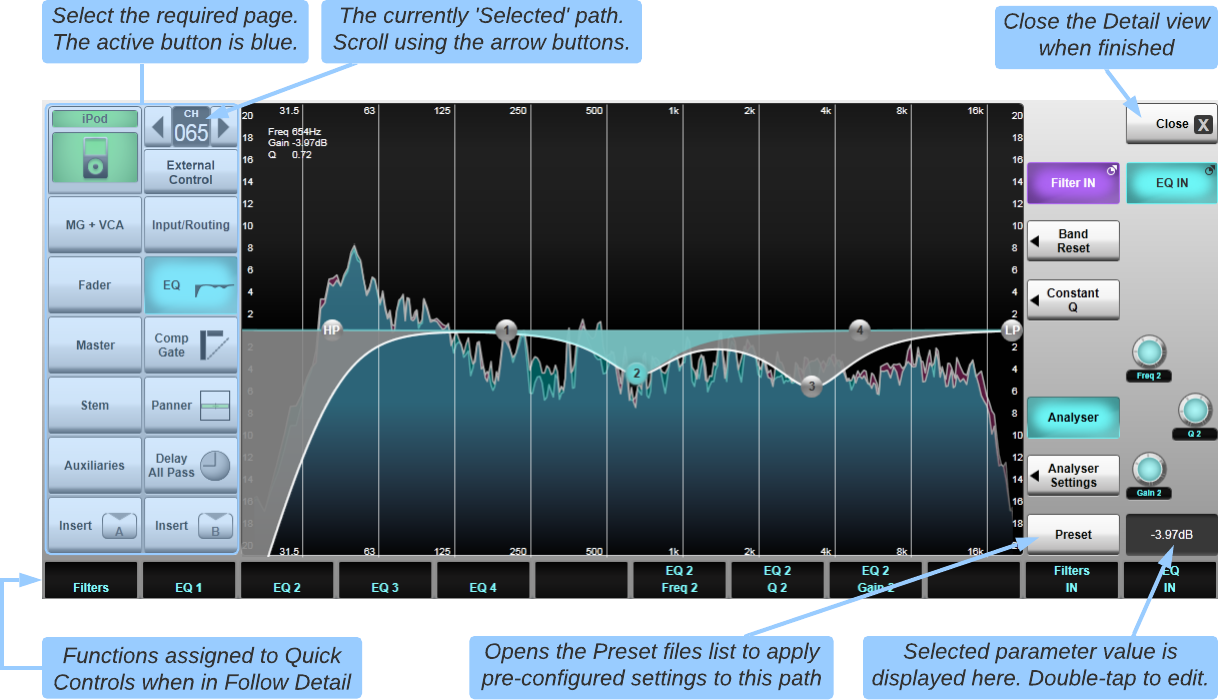
Double-tap the quick display 'thumbnail' in the middle of the channel strip to open the Detail View page corresponding to the function currently visible in the quick display, e.g. EQ in the example below.
Or double-tap the Eyeconix image and colour at the bottom of the Channel View to open the path colour and name (path configuration) Detail View page.
Elements may now be adjusted by pressing or dragging the touchscreen.
Tapping on an element (e.g. an EQ node or a fader) will give focus to that element. Controls in the lower right corner of the Detail View allow manipulation of the selected parameter(s).
For example, tapping the node for EQ band 2 as in the example image above has assigned the Frequency, Q and Gain for that EQ band to the three on-screen encoders to the right of the graph.
Double-tapping the text field beneath the encoders will bring up a keyboard, allowing a precise value to be entered for the last touched parameter.
Config/Eyeconix
Path names, Eyeconix and colours all provide ways of distinguishing visually between individual paths, in addition to the path number and type indication at the top of the on-screen channel strip.
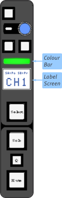
Path names are shown in the path Label Screens above the Select buttons in the Fader Tile.
By default, paths are simply named according to their type and number.
Path colours are shown in the Colour Bars above the path Label Screens, as well as at the top and bottom of the on-screen path in Channel View.
Path Eyeconix are simply graphics displayed at the bottom of the on-screen path in Channel View, symbolising the path source.
These path display elements can be configured in the Detail View, opened by double-tapping in the Eyeconix area at the base of the path:
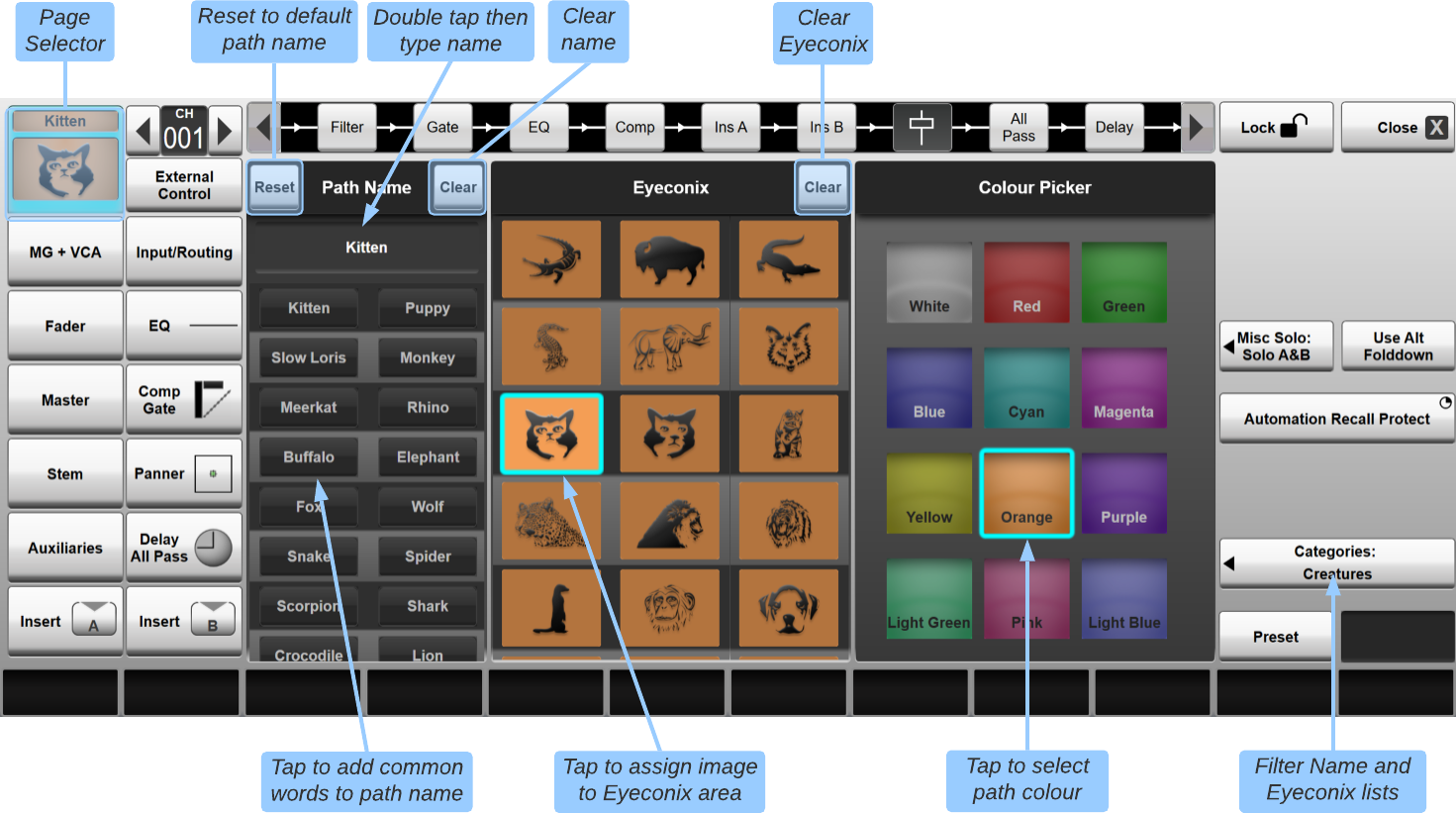
The Categories button in the right side of the page allows you to filter the images and words shown according to subject – touch it and select a category from the list which appears.
The Preset button (bottom right corner) opens the Preset page which can be used to load or save an entire channel strip
of settings.
This preset will include the following settings:
- Path Name
- Eyeconix Image
- Path Colour
- Fader level
- Filter settings
- EQ settings
- Compressor settings
- Gate settings
- Panning
- Delay
- All Pass Filter settings
(See Presets for more information)
Naming a Channel
By default, channels are named according to type (CH for input channel, AUX, STEM or MASTER) and number.
To rename the channel, double-tap the label area beneath the Channel Name title – a keyboard will appear; type the new name and touch OK (or touch the red X to close the keyboard and discard any changes).
The Next and Prev buttons on the keyboard popup (Tab and Shift+Tab respectively if using a USB keyboard) allow quick scrolling through contiguous channels without having to close and re-open the keyboard between each channel.
To reset the name back to the channel number and type, touch Reset (to the left of the Channel Name title);
To clear the label completely, touch Clear (to the right of the Channel Name title).
You can also quickly insert words from the list shown below the label area – simply touch a word to insert it at the end of the current label.
The Categories button in the right side of the page allows you to filter the words shown according to subject – touch it and select a category from the list which appears.
Selecting Eyeconix
A list of images is shown in the centre of the Detail View. Simply touch on the required image to select it – it will appear in the channel Eyeconix area.
To scroll the image display, touch the image area and swipe up or down.
The Categories button in the right side of the page allows you to filter the images shown according to subject – touch it and select a category from the list which appears.
To clear the currently selected image and leave the channel Eyeconix area blank, touch the Clear button beside the Eyeconix title.
Selecting Colours
To select a different colour for the channel, touch on the required colour from the palette shown in the right of the Detail View – the name area at the top and bottom of the on-screen channel will change to that colour, as will the colour bar above the channel's Label Screen.
Note: The graphic across the top of this page of the Detail View is used for altering the channel's processing order. See Processing Order for more details.
Control Tile
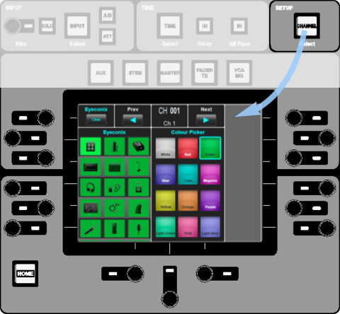
Basic Eyeconix and Colour selection can be assigned to the Control Tile by pressing the Channel button above and to the right of the Control Tile Screen:
The selected channel is shown at the top of the screen; the Prev and Next arrow buttons either side of it can be used to scroll channels.
Colours are listed on the right, with Eyeconix images listed on the left; swipe the screen up or down to scroll the Eyeconix list.
To select an image or colour, simply touch it in the screen.
To clear the Eyeconix image, touch the Clear button in the top left corner (or press the adjacent encoder).
Input/Routing
You can configure and route a path's inputs and outputs in the Input/Routing page of the Detail View.
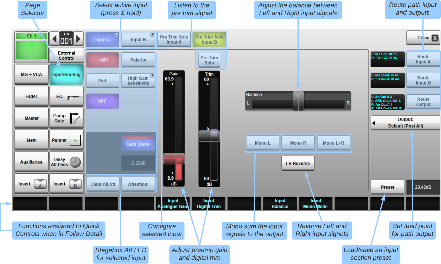
As each Channel has two inputs, ensure that the correct input's button (Input A or Input B, at the top of the Detail window) is lit blue.
If it isn't, press & hold the correct button.
Refer to the next section on Routing for further details on routing inputs and outputs.
The current route(s) are displayed to the left of the Route buttons.
If the input signal is not what you expect it to be, activate the Attention! button (only available when routed to an SSL stagebox).
This illuminates the ATT light on the stagebox socket routed to that input, providing indication to technical personnel on the stage that the input needs checking.
You can cancel all ATT lights by pressing Attention Clear All.
You can use the Pre Trim Solo Input A and Pre Trim Solo Input B buttons to audition the incoming signal before switching inputs.
The Pre Trim Solo button solos whichever input is currently active (Input A, Input B or the Live Recorder Record Return if in
Rehearse Mode).
Many of the remaining controls are only applicable if the Channel is routed to the local mic inputs or an SSL Network I/O or ML stagebox mic pre.
Non-SSL stageboxes, AES and analogue line inputs will have a limited set of controls. The remainder of this section assumes that a SSL mic pre is being used.
In the main part of the page there are controls to turn on +48V phantom power and invert the input's Polarity.
When using the local Analogue inputs or an ML32.32 stagebox, there are controls to insert the 20 dB Pad and activate the analogue HPF (70 Hz, 6 dB per octave High Pass Filter).
The High Gain Sensitivity button (press & hold to activate) increases the input sensitivity of the preamp by +15 dB for particularly quiet sources.
When using Net I/O Stagebox inputs, there is a Pad (20 dB for SB i16 and SB 8.8 stageboxes; 30 dB for SB 16.12 and SB 32.24 stageboxes),
a Mic/Line switch (engage Mic for mic mode, disengage for line mode), Input Mute and Aud (Audition, SB 8.8 & i16 only)
and Lim (Limiter, SB 8.8 & i16 only).
For more information on Net I/O Stageboxes please refer to the Net I/O Stageboxes section.
Note: Controls which are not relevant to the input type will be greyed out. Find out how to make routes in Routing.
You can then adjust the analogue gain using the Gain control and introduce a digital signal Trim using the sliders to the right of the input buttons.
Important Note: If the same stagebox/local analogue input is routed into multiple Input Channels and/or Talkback Channels,
then each of those channels may have control of the same set of parameters associated with that analogue input (gain, pad etc.) and will therefore remain synchronised with one another.
Control of those parameters may be automated per-channel under the 'Input' filter section, but differences in the automated states of those shared analogue input parameters
may inadvertently be introduced if the channels are not dropped in or out of Store and Recall scope together.
Firing a scene with such differences in it may result in undesired behaviour of the analogue input's parameters.
Data generated during the initialisation of routing analogue inputs to channels is specific to each channel, not per analogue input. Care must therefore be taken to ensure this data is explicitly stored for each channel.
The Balance control becomes active on stereo channels and adjusts the level balance between the Left and Right input signals.
The Mono L, Mono R and Mono L+R
buttons can be used to reroute the incoming Left and Right signals to the remainder of the channel processing.
For example, the Left input can be routed to both halves of a stereo channel if the Right input becomes noisy.
Alternatively, a stereo keyboard channel could be configured in a festival situation,
but certain acts may only bring a mono keyboard, in which case the Mono L
button can simply be pressed without the need to reroute or reformat the channel.
For stereo channels only, the LR Reverse button will reverse the left and right input signals.
Tap Route Output to route the output of a channel. Note that this send is always before panning has been applied to the signal.
The output feed point can be adjusted by tapping Output: and choosing one of the options
(Post Trim, Pre Fader, Post Fader and Post All).
The default output feed point of an Input Channel can be customised in
Menu > Setup > Options > System tab.
New Input Channels will be created with the default output feed point.
Quick Controls
Head amp and trim controls are available directly on the Fader Tile Quick Controls. Tap the top section on the channel strip in the Channel View screen or press & hold the Fader Tile's Quick Control Up arrow to assign the Input section to the controls.
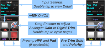
Press any Quick Control encoder to cycle through the three available pages: Analogue (red), Digital Trim (blue) and Routing (cyan).
In the analogue and digital pages, the context display shows gain, trim, phantom, pad, polarity, etc., where applicable. The top of the main screen displays analogue gain in red or digital trim in blue when their pages are active.
In the analogue page, the keys available are +48V, HPF (preamp's high pass filter; local I/O and MADI stageboxes only),
and Pad. The encoder controls analogue Gain.
In the digital page, pre-trim Solo and Polarity are available. The encoder controls digital Trim.
Note: Analogue controls are available when an analogue input has been routed to the channel.
Digital trim is available on all Channels, Stems, Auxes, Masters, and Matrix output paths.
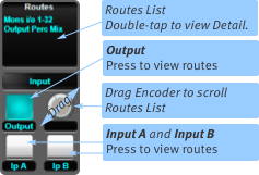
Routing provides a quick view of existing channel input and output routes in the context display across the middle of the main screen.
The keys switch between Input A, Input B and Output routing views.
Note that the keys do not switch between Inputs A and B.
Note: All channel Direct Output feed points are user-definable. The default is set in the SYSTEM tab of the Options menu
and the Direct Output feed point can be set for each channel individually from the Input/Routing page of the Detail View.
Control Tile
Channel path input controls are available via the Control Tile to the right of the Main Screen.
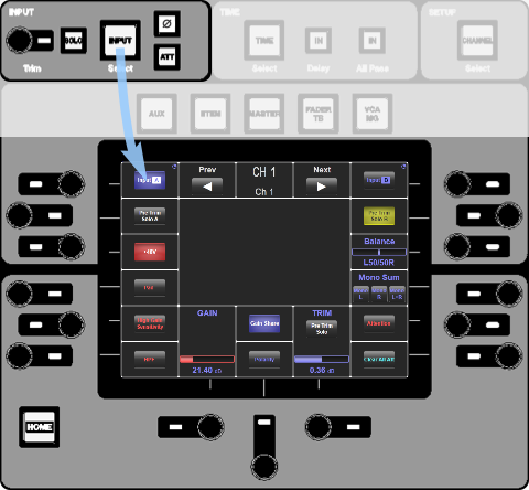
Press the Input button beneath the console logo to assign Input functions to the Control Tile Screen:
The encoders around the screen are assigned to the functions in the screen area nearest to them.
Switches/buttons are operated by pressing the encoder. Continuous parameters are changed by turning the encoder.
The LED next to each encoder is lit whenever the encoder is assigned to any on-screen parameters. If the encoder is only assigned to a switch, the LED colour also indicates the state of the switch.
All on-screen buttons can also be controlled by touching the screen.
The controls around the Input button beneath the console logo provide access to essential input elements, and these remain active regardless of whether Input functions are assigned to the Control Tile screen.
Gain Sharing
MADI and Dante stagebox inputs can 'shared' by routing to multiple consoles. One console is always designated the 'Master' with control over the preamp settings.
Other consoles may receive the audio but will not be able to control the preamp.
See the Gain Sharing section for further details.
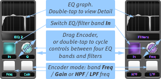
EQ
The EQ page contains the controls for the High and Low Pass Filters and the 4 Band Parametric EQ.
To find out more about the Filters and EQ please see Path Processing.
Comp/Gate
The Comp/Gate page contains the controls for the Compressor and the Gate.
To find out more about the Compressor and the Gate please see Path Processing.
Panner
Open the Detail View and tap on the Panner page.
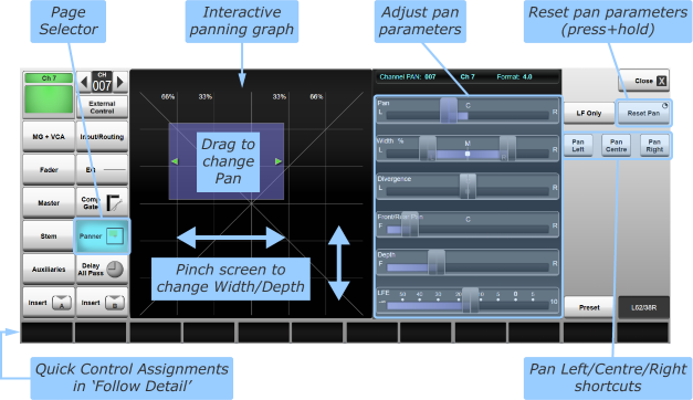
The graph on the left side of the page represents the pannable area, with the blue square indicating where the audio is placed in space.
Drag the square around the graph to pan the signal around the space.
Pinch the graph area horizontally to adjust the width of the signal (not applicable to mono paths). The arrows at the edge of the blue area will be coloured red if the width has been inverted (L-R swap) or green if not inverted.
Sliders for all relevant pan parameters are also found in the right side of the page – drag the sliders with your finger, or use the Quick Controls beneath the screen to adjust them.
Notes:
The parameters available depends on the formats of the channel and the bus being routed to.
The Width of a signal is limited by the value of the Pan parameter.
Moving the Pan slider Left/Right will automatically reduce the Width (and the Width will be restored if Panning back towards the centre if no other controls have been touched).
Similarly, adjusting the Front/Rear Pan will automatically reduce the Depth of the signal.
To re-centre the pan, press & hold Reset Pan (towards the top right of the Detail View).
Use the Pan Left and Pan Right shortcut buttons to quickly set the Pan fully Left or Right.
Use the Pan Centre button to set the Pan back to the centre (the previous Width value will be preserved).
The LF Only button, when engaged, will route only the LF channel to 5.1 buses.
LF Only is only active when viewing a path that is not 5.1 (i.e. a path that does not contain an LF channel) and that path is routed to at least one 5.1 bus.
If a 4.0 or 5.1 path is assigned to one or more 4.0 or 5.1 buses, a Front/Rear Depth control will also be visible.
Pinch vertically on the panning graph to adjust Front/Rear Depth or alternatively, use the corresponding slider to the right.
Note: Panning is applied at the point the channel is routed onto a bus.
This allows each Aux/Stem mix to have independent pan settings; see the Bus Routing & VCAs page for more details.
Direct outputs and post-all meters use the 'pre'-panned signal.
Quick Controls
Basic pan control is available in each channel strip. To access the basic in-channel pan controls, select the Pan Assign button in the Channel View:

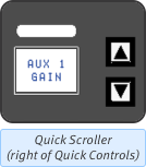
You can also scroll the Assign functions using the Quick Scroller to the right of the Fader Tile Quick Controls – the current function is shown in its Label Screen, as well as by the appropriate button being lit in the Channel View channel strip.
Tip: Press & hold the down arrow button to jump to the Pan section.
Basic pan controls will appear in the Quick Control Area.
The Context display shows the current pan position. A simplified version of this graph is also shown in the Pan Assign button-cap, which will stay visible when the Quick Display isn't showing pan information.
The Quick Control buttons define the parameter assigned to the Encoder: Pan position, Width, or Divergence.
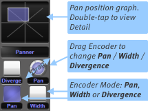
Press the Quick Control encoder on the Fader Tile (or double-tap the on-screen encoder) to access the surround pan controls; Front/Rear Pan, Depth, and LFE Gain.
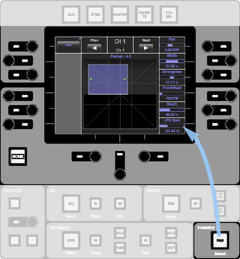
Control Tile
Channel Pan configuration is available via the Control Tile to the right of the Main Screen.
Press the Pan button beneath and to the right of the Control Tile Screen:
Delay/All Pass
The Delay/All Pass page contains the controls for the Delay and the All Pass Filter.
To find out more about the Delay and the All Pass Filter please see Path Processing.
MG + VCA
A path can be assigned to a Mute Group or VCA from the MG + VCA page.
To find out more please see Mute & Mute Groups and Bus Routing & VCAs.
Fader Detail
Open the Detail View and tap on the Fader page.
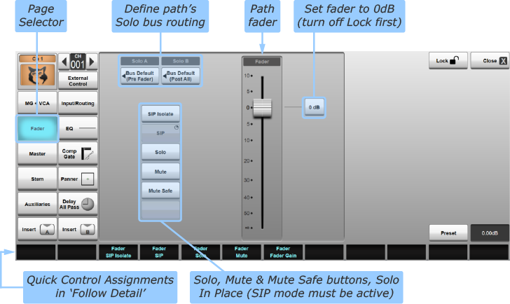
The Lock button in the top right corner of the Detail page will prevent any parameters on the Fader Detail page from being changed. Ensure it is deactivated to make any necessary adjustments and re-enable once finished to prevent accidental changes.
Note: This Detail page also allows you to configure the way in which the channel feeds to solo buses,
using the Solo A and Solo B buttons.
If Solo In Place mode is active, channels can also be isolated from SIP here. See Solos for more details.
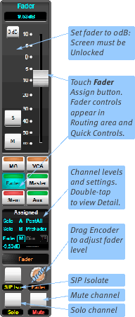
Quick Controls
It is also possible to display channel faders in the Assignment area of the Channel View. This is primarily intended for use with SOLSA Offline Software.
To view channel faders on the screen, select the Fader Assign button in the Channel View:

Fader will appear on the screen, along with its Solo (S) and Mute (M) buttons, and a 0 dB button which sets the fader to 0 dB.
Mute, Solo and Gain functions will also be assigned to the channel Quick Controls, as shown on the right.
Control Tile
The Fader controls can also be shown in the Control Tile by pressing the Fader / TB button immediately above the Control Tile Screen.
The encoders around the screen are assigned to the functions in the screen area nearest to them.
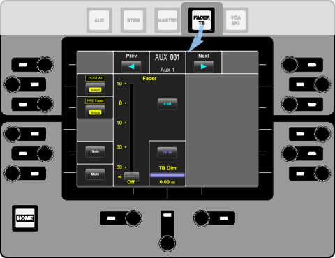
Switches are operated by pressing the encoder, and continuous parameters are changed by turning the encoder.
The LED next to each encoder is lit whenever the encoder is assigned to any on-screen parameters. If the encoder is only assigned to a switch, the LED colour also indicates the state of the switch.
All on-screen buttons can also be controlled by touching the screen.
Most of these controls function exactly as they do in the Detail display, with the exception of the
Solo 1 and Solo 2 buttons which cycle through
Bus Default, None, Pre Fader and Post All, as indicated immediately above each button.
Master
A path can be assigned to a Master from the Master page.
To find out more please see Bus Routing & VCAs.
Stem
A path can be assigned to a Stem from the Stem page.
To find out more please see Bus Routing & VCAs.
Auxiliaries
A path can be assigned to an Aux from the Auxiliaries page.
To find out more please see Bus Routing & VCAs.
Insert A/Insert B
Every path has two insert points, each of which can be routed to external I/O or to the modules within the console's internal Effects Rack, as well as a variety of other locations.
If there is an Insert routed to either Insert A or B, the Effect can be accessed and routed using these buttons.
Note: All path types, including Dry Paths, have two insert points.
By default both Insert points are pre-fader.
Note: Inserts can be moved within the processing order by going to the Eyeconix Detail View, muting the channel, unlocking the Detail View screen and dragging the channel elements in the display across the top of the page; see Processing Order for more details.
Routing an Insert
Routing Inserts is covered in Effects Rack Overview.
Detail View Control
Once a module is routed to a channel Insert, the module will appear within that Insert's Detail View, which you can access from within the page by pressing the Insert A or Insert B button at the bottom of the page selectors. This page is a duplicate of the Effects Rack's module page:
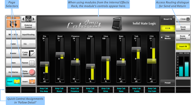 Note: This page will be empty if nothing has been routed to the Insert point. A 'Manual Routing' graphic will be shown if not all of the send and return routes have been made or if they are routed to external devices, for which there is no internal control available.
Activate the insert's routing by touching the Insert IN button below the routing buttons on the right. The rest of the controls are module-specific and are covered in the Effects Rack pages of these help screens.
The Quick Controls can also be assigned to the Detail View parameters by activating Follow Detail mode. Touch the Follow Detail button (bottom right corner of the Main Screen) to toggle between Follow Channel (button inactive) and Follow Detail (button active). The labels across the bottom of the screen indicate the function which is then assigned to the Quick Controls beneath them. As a general rule only one function is assigned to each Channel's Quick Controls. Switch functions are assigned to the Upper Quick Key (which will be lit if available) and continuous parameters are assigned to the Encoder.
Notes:
The Inserts can also be routed to external effects or other buses/channels within the console. In these instances the Insert Detail page will display a Manual Routing graphic to indicate that it is routed but no Detail View control is available.
The Detail page will be blank if nothing has been routed to/from the Insert.
Quick Controls
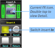
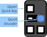
Once routed, inserts can be switched in and out using the Upper Quick Key:
When a module from the internal Effects Rack is routed, its icon will also appear in the Context display.
Control Tile
Once routed to an internal Effects Rack module, the module can also be controlled from the Control Tile.
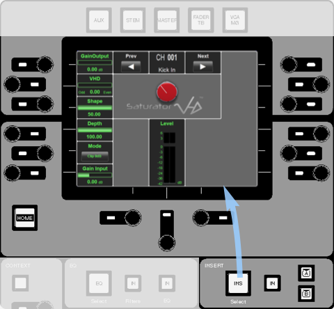
Press the Insert button below the Control Tile Screen to assign insert control to the Control Tile.
The A IN and B IN buttons in the Insert area below the screen can then be used to switch between Insert A and B.
The IN button in the Insert area below the screen switches the currently displayed insert in and out.
The encoders around the screen are assigned to the functions in the screen area nearest to them.
Switches are operated by pressing the encoder, and continuous parameters are changed by turning the encoder.
The LED next to each encoder is lit whenever the encoder is assigned to any on-screen parameters. If the encoder is only assigned to a switch, the LED colour also indicates the state of the switch.
All on-screen buttons can also be controlled by touching the screen.
Note: If the insert is not routed to an internal Effects Rack module the Control Tile Screen will show a 'Manual Routing' graphic and will be blank if nothing is routed to/from the Insert.
External Control
Control of external devices can be accessed from this page.
Please refer to the External Control section for further details.