
The following pages contain instructions on setting up SSL Live consoles for use with a Dante network, routing to and from Dante devices and controlling and gain sharing with SSL Net I/O Stageboxes:
- Setting Up Dante
- Virtual Tie Lines
- Dual Domain Routes and Configuring Dante Devices
- Network I/O Stageboxes and Devices
- BLII & X-Light Bridges (this page)

The Net I/O BL II Bridge is a 1U rack-mount device which converts between high channel count Dante and SSL's proprietary BlackLight™ digital multichannel audio format. It provides 256 redundant bidirectional uncompressed audio channels from an SSL BLII and Dante equipped Live console to/from Dante networks at 24-bit, at either 96 kHz or 48 kHz resolution.
The BLII Bridge is designed to be located near the console and can only be used by one console at any one time.
The Net I/O BLII Bridge is compatible with all BLII and Dante equipped SSL Live consoles running software version 4.5 or later and supports the AES67 and SMPTE 2110-30 AoIP network transport standards.
Notes:Please be aware of network bandwidth when using a BLII Bridge on a Dante network. 10 Gigabit uplinks between switches may be required on networks involving a BLII Bridge and large amounts of I/O.
Front Panel LEDs
There are four LED indicators on the front panel of the BLII Bridge: PSU, BL S, SRC and NET S for indicating power supply and clocking status.
| LED | Off | Solid Red | Flashing Green & Red | Flashing Green | Solid Green |
|---|---|---|---|---|---|
| PSU | Both PSUs are off | Only one PSU is functioning correctly | N/A | N/A | Both PSUs functioning correctly |
| BL S | BLII Bridge not set to Sync to External BLII source and/or not connected to console | N/A | N/A | Resyncing - searching for a valid clock source | Clocked to BLII and incoming clock source present |
| SRC | Device synced to a clock source | Device is resyncing (searching for a valid clock source) | N/A | N/A | N/A |
| NET S | Not configured to clock from Dante network | Unit it set to clock from Dante network but there is no network connected | Primary or Secondary network port not connected | Resyncing - searching for a valid clock source | Set to clock from Dante network and Leader Clock on network detected |
NOTE: When NetS is Flashing Red - Unit is PTPv1 Clock Leader only/AES67 disabled
Front Panel Connections
One pair of SFP cages is located on the front panel for Dante network connectivity:
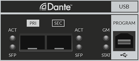
These will be pre-populated with RJ45 but can alternatively be populated with single-mode or multi-mode fibre SFPs.
The status LED meanings are as follows:
| LED | Off | Flashing Red | Flashing Green & Red | Flashing Green | Solid Green |
|---|---|---|---|---|---|
| ACT | Unit is off | N/A | Unit is on | N/A | N/A |
| SFP | No SFP fitted | N/A | N/A | N/A | SFP fitted |
| GM | Unit is not GM (or both Dante Pri and Sec disconnected) |
PTPv2 GM only | N/A | PTPv1 GM only | PTPv1 and PTPv2 GM |
| STAT | Hardware fault | Audio muted. The BLII Bridge automatically mutes audio during resyncing |
N/A | Hardware OK | N/A |
The Program USB port is for performing updates to the unit. Instructions on updating the BLII Bridge will accompany all relevant update packages.
Rear Panel Connections
The BLII Bridge incorporates a pair of redundant power supplies, which are powered from the pair of IEC connections on the back of the unit.
Two pairs of SFP cages is located on the back panel. One pair will be pre-populated with multi-mode LC fibre SFPs but can alternatively be populated with single-mode SFPs.
HC Link 1 Port A Main and Backup are used for connecting to BLII 1a and 1b (or 2a and 2b) ports on the console respectively.
Port B is not in use.
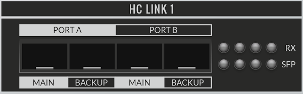
There is also an RX and SFP status LED for each port. The leftmost pair of RX and SFP LEDs refer to Port A Main and the second from the left refers to Port A Backup. The third and fourth from the left pairs of LEDs refer to Port B, which is not in use.
The status LED meanings are as follows:
| LED | Off | Solid Red | Flashing Green | Solid Green |
|---|---|---|---|---|
| RX | N/A | Port is not connected | Port is connected and is Active port in redundant connection |
Port is connected and is Inactive port in redundant connection |
| SFP | No SFP fitted | N/A | N/A | SFP fitted |
Connecting BLII Bridge to SSL Live Consoles
The following equipment is required to connect a BLII Bridge to an SSL Live console.
- An SSL Live console
-
- with at least one redundant pair of BLII ports fitted
- and with a Dante Expander module fitted (if you are interested in a Dante Expander retrofit please contact support@solidstatelogic.com)
- A BLII Bridge
- At least one network switch (non-redundant). At least two switches (primary and secondary) are required for a fully redundant connection.
Connect the console's BLII port 1a to HC Link Port A Main on the back of the BLII Bridge via multi-mode LC fibre.*
Connect the console's BLII port 1b to HC Link Port A Backup on the back of the BLII Bridge via LC fibre.*
*or single-mode LC fibre if the console has been fitted with single-mode BLII ports and single-mode SFPs have been fitted to the BLII Bridge - not standard.
Notes:If using an L500 Plus with two pairs of BLII ports fitted, either redundant pair can be used to connect to the BLII Bridge. The other pair can be used to connect to a BL II-MADI Concentrator or another BLII Bridge.
Connect the BLII Bridge Dante Primary and Secondary ports to the primary and secondary Dante network switches respectively.
Connect the console's Dante Expander Primary and Secondary ports to the primary and secondary Dante network switches respectively. You must also connect the Dante Expander to the Dante network. Dante device control cannot pass down a BLII connection, so connecting the Dante Expander allows the console to have control over Dante devices and create routes on the network.
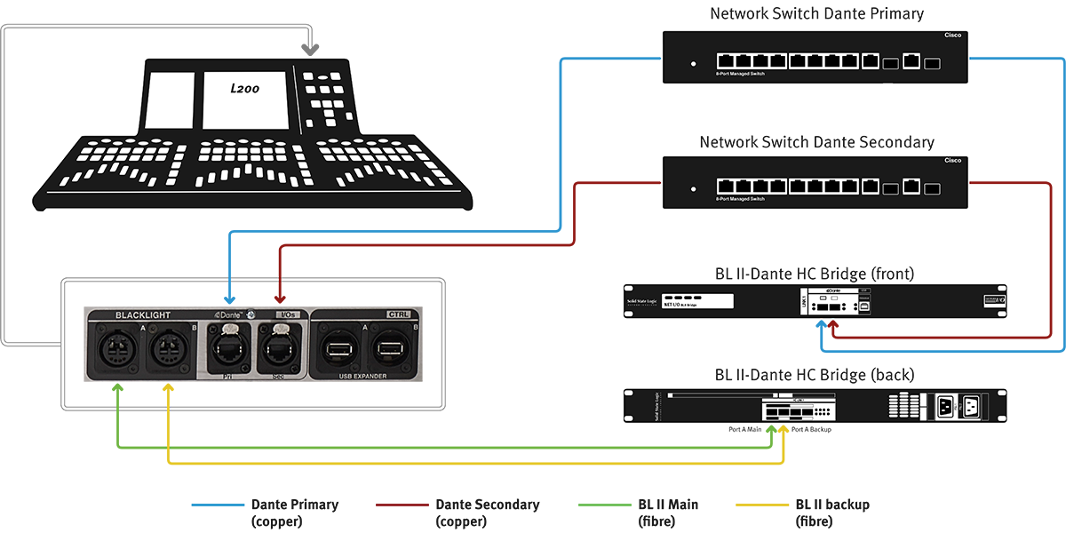
Connect your Network I/O stageboxes to your Dante primary and secondary network switches, taking care not to cross over primary and secondary networks anywhere.
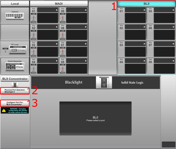
Setting Up the BLII Bridge with an SSL Live Console
On the console go to MENU > Setup > I/O > Local/MADI Configuration.
If there are no devices configured in the relevant port when the BLII Bridge is connected, the BLII Bridge will be automatically detected and configured.
If there are already devices configured in the relevant port, the port will need to be manually configured.
To configure the port:
- Tap on the relevant port column heading to view settings for the port.
- Press & hold Physical Port Selection: in the Detail View of the port and select Blacklight II.
- Press & hold Configure Port For: and select Net I/O BLII Bridge.
 Caution:
Take care when reconfiguring the BLII port as routes will be unmade.
- If reconfiguring the BLII port from BLII-MADI Concentrator to BLII Bridge, all existing routes between the console and devices connected via the BLII-MADI Concentrator will be unmade.
- If reconfiguring the BLII port from BLII Bridge to BLII-MADI Concentrator, ALL Dante dual domain routes will be unmade regardless of whether they route through the BLII Bridge or the Dante Expander Module. Virtual Tie Line routes made to the Dante Expander Module will remain.
- The console may also need to be re-clocked when changing port configuration. See the clocking section below.
BLII port configuration is stored in showfiles.
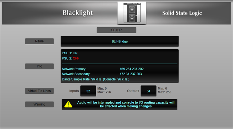
In order for the BLII Bridge to function correctly, the name of the BLII Bridge on the console must match the name of the unit in Dante Controller.
Ordinarily the BLII Bridge name will be automatically populated when it is detected on the network by the console software. However, if this does not occur, the name can be entered manually.
First, open Dante Controller on a computer and connect it to the Dante network (or to the BLII Bridge's Dante Primary port directly using a network cable).
Check that the BLII Bridge appears in Dante Controller. (For more information on IP addresses and connecting Dante devices to the network, please see the Setting Up Dante section).
To edit the BLII Bridge name in Dante Controller, double click on the BLII Bridge and go to the Device Config tab. At the top of the page under Rename Device, type in a name and press Apply. You will be asked to confirm the name change. Click Yes. Please note that changing the Dante name of a device breaks all existing routes to/from this device.
Set the BLII Bridge name on the console to match the name used in Dante Controller exactly.
Reboot the console.
PSU status, network status, and Sample Rate are also displayed here.

The Net I/O X-Light Bridge is a 1U rack-mount device which converts between high channel count Dante and SSL's proprietary X-Light digital multichannel audio format. It provides 256 redundant bidirectional uncompressed audio channels from an SSL X-Light equipped Live console to/from Dante networks at 24-bit, at either 96 kHz or 48 kHz resolution.
The X-Light Bridge is designed to be located on stage and can only be used by one console at any one time.
The X-Light Bridge is compatible with all X-Light equipped SSL Live consoles running software version 4.8 or later and supports the AES67 and SMPTE 2110-30 AoIP network transport standards.
Notes:Please be aware of network bandwidth when using an X-Light Bridge on a Dante network. 10 Gigabit uplinks between switches may be required on networks involving an X-Light Bridge and large amounts of I/O.
Front Panel Connections
One pair of redundant X-Light ports is located on the front panel for connection to an SSL Live console:

Front Panel LEDs
There are eight LED indicators on the front panel of the X-Light Bridge: PSU, XL S, SRC, NET S for indicating power supply and clocking status...
| LED | Off | Solid Red | Flashing Green & Red | Flashing Green | Solid Green |
|---|---|---|---|---|---|
| PSU | Both PSUs are off | Only one PSU is functioning correctly | N/A | N/A | Both PSUs functioning correctly |
| XL S | X-Light Bridge not set to Sync to External X-Light source and/or not connected to console | N/A | N/A | Resyncing - searching for a valid clock source | Clocked to X-Light and incoming clock source present |
| SRC | Device synced to a clock source | Device is resyncing (searching for a valid clock source) | N/A | N/A | N/A |
| NET S | Not configured to clock from Dante network | Unit it set to clock from Dante network but there is no network connected | Primary or Secondary network port not connected | Resyncing - searching for a valid clock source | Set to clock from Dante network and Leader Clock on network detected |
NOTE: When NetS is Flashing Red - Unit is PTPv1 Clock Leader only/AES67 disabled
...and two pairs of AUDIO and LINK LEDs to show the status of the MAIN and BACKUP X-Light fibre connections to the console.
| LED | Solid Red | Flashing Green | Solid Green |
|---|---|---|---|
| AUDIO MAIN | No Main connection to console via X-Light fibre | Main Audio connection to console is good and is the active connection | Main Audio connection to console is good (backup) |
| LINK MAIN | N/A | Main Link connection to console is good | N/A |
| AUDIO BACKUP | No Backup connection to console via X-Light fibre | Backup Audio connection to console is good and is the active connection | Backup Audio connection to console is good (backup) |
| LINK BACKUP | N/A | Backup Link connection to console is good | N/A |
Rear Panel Connections
The X-Light Bridge incorporates a pair of redundant power supplies, which are powered from the pair of IEC connections on the back of the unit.
Two pairs of redundant network connections are provided on the rear panel. The PRI and SEC Dante AUDIO pair transport up to 256x256 channels of audio between the Dante network and the console's X-Light ports. The other pair, labelled CONSOLE LINK PRI and SEC provide a control link from the console for stagebox control and expose the console's local Dante audio channels and anything connected to the console's local Dante ports to the rest of the network, e.g. for playback/recording devices located close to the console.
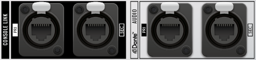
Both Dante AUDIO and CONSOLE LINK ports should be connected to your network switches for correct operation.
Connecting X-Light Bridge to SSL Live Consoles
The following equipment is required to connect Network I/O stageboxes to an SSL Live console via an X-Light Bridge:
- An SSL Live console with X-Light ports fitted
- An X-Light Bridge
- At least one network switch (non-redundant). At least two switches (primary and secondary) are required for a fully redundant connection
- A number of SSL Network I/O Dante stageboxes
Connect the console's X-Light port Main to Main on the front of the X-Light Bridge.
Connect the console's X-Light port Backup to Backup on the front of the X-Light Bridge.
Connect the X-Light Bridge's Dante AUDIO PRI and CONSOLE LINK PRI ports on the rear of the unit to your Dante primary network switch.
Connect the X-Light Bridge's Dante AUDIO SEC and CONSOLE LINK SEC ports on the rear of the unit to your Dante secondary network switch.
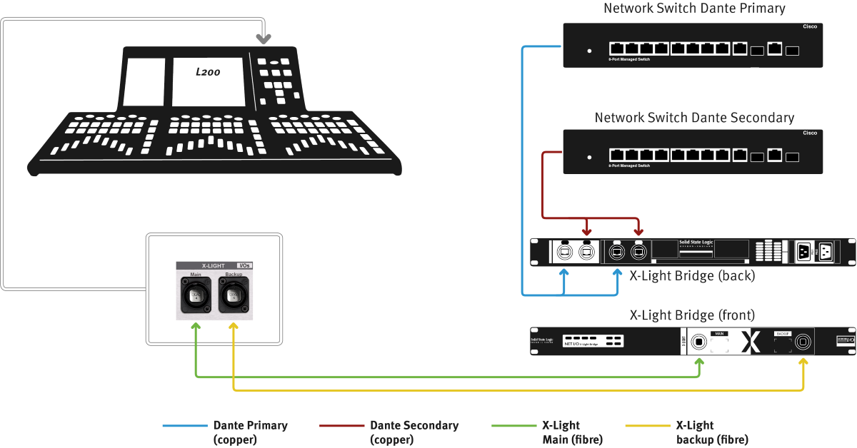
Connect your Network I/O stageboxes to your Dante primary and secondary network switches, taking care not to cross over primary and secondary networks anywhere.
Setting Up the X-Light Bridge with an SSL Live Console
On the console go to MENU > Setup > I/O > Local/MADI Configuration.
If there are no devices configured in the relevant port when the X-Light Bridge is connected, the X-Light Bridge will be automatically detected and configured.
If there are already devices configured in the relevant port, the port will need to be manually configured.
To configure the port:
- For L100, L200 and L350 consoles, tap on the BLII port column heading to view settings for the BLII port. For L450, L550 and L650, tap on the second BLII/X-Light port heading (the right-most column in the I/O page)
- Press & hold Physical Port Selection: in the Detail View of the port and select X-Light.
- X-Light Bridge will be automatically configured in the Configure Port For: section.
Caution:Take care when reconfiguring the BLII/X-Light port as routes will be unmade.
Virtual Tie Line routes made to the Dante Expander Module will remain.
The console may also need to be re-clocked when changing port configuration. See the clocking section below.
X-Light port configuration is stored in showfiles.
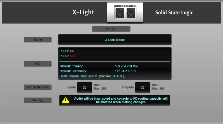
In order for the X-Light Bridge to function correctly, the name of the X-Light Bridge on the console must match the name of the unit in Dante Controller.
Ordinarily the X-Light Bridge name will be automatically populated when it is detected on the network by the console software. However, if this does not occur, the name can be entered manually.
First, open Dante Controller on a computer and connect it to the Dante network (or to the X-Light Bridge's Dante Audio Primary port directly using a network cable).
Check that the X-Light Bridge appears in Dante Controller. (For more information on IP addresses and connecting Dante devices to the network, please see the Setting Up Dante section).
To edit the X-Light Bridge name in Dante Controller, double click on the X-Light Bridge and go to the Device Config tab. At the top of the page under Rename Device, type in a name and press Apply. You will be asked to confirm the name change. Click Yes. Please note that changing the Dante name of a device breaks all existing routes to/from this device.
Set the X-Light Bridge name on the console to match the name used in Dante Controller exactly.
Reboot the console.
PSU status, network status, and Sample Rate are also displayed here.
IP Addresses
When BLII/X-Light Bridges are shipped from SSL, they will be set to DHCP.
The BLII/X-Light Bridge's IP address must be in the same subnet as the Dante Expander module and the console's Dante Control Settings. For more information about IP addresses and subnets please see Setting Up Dante.
Please note:The console's Dante Expander module must also be set to an IP address within the same subnet as the BLII/X-Light Bridge and the console's Dante Control Settings.
Changing the IP address of the BLII/X-Light Bridge and Dante Expander Module
The BLII/X-Light Bridge and Dante Expander's IP addresses are changed in Dante Controller. Double click on the device and go to the Network Config tab. Choose either Obtain an IP Address Automatically or Manually configure an IP address. If you select Manually configure an IP address, type in an IP address and a Netmask (also known as subnet mask).
Click Apply. You will be asked to confirm the IP address configuration change. Click Yes. The BLII Bridge must be rebooted in order for these changes to take effect. Click Reboot at the bottom of the window. You will be asked to confirm the reboot. Click Yes.
Changing the IP address of the console's Dante Control Settings
On the console, go to MENU > Setup > Options > NETWORK tab. In the DANTE CONTROL SETTINGS section, the console's Dante Control IP Settings are listed. Choose either DHCP or Fixed IP addresses. If you choose Fixed, double tap on the IP Address and Netmask (also known as subnet mask) fields to edit them. Press and hold Apply.
Clocking
Please refer to the BLII/X-Light Bridge section of the Clocking page to correctly configure the console, BLII/X-Light Bridge and network clocking for correct operation.
Sample Rate
The sample rate of the BLII/X-Light Bridge must match the sample rate of the console.
The Sample Rate is changed in Dante Controller. Double click on the BLII/X-Light Bridge and go to the Device Config tab. In the Sample Rate section, click on the drop down menu and select the desired sample rate. You will be asked to confirm the sample rate change. Click Yes.
The BLII/X-Light Bridge must be rebooted in order for this change to take effect. Click Reboot at the bottom of the window. You will be asked to confirm the reboot. Click Yes.
If working with multiple sample rates on the same network, as well as a BLII/X-Light Bridge, the following instructions must be followed.
The BLII/X-Light Bridge and the console must ALWAYS be running on the same sample rate.
To interface with devices on a different sample rate on the same network, these devices must be routed to/from the console via Virtual Tie Lines through the Dante Expander Module.
Go to MENU > Setup > I/O > Local/MADI Configuration and tap on the Dante Expander.
Double tap on the Virtual Tie Lines quantity and type 32 (maximum quantity when either console or Dante Expander or both are running at 96 kHz). Now engage SRC In.
32 Virtual Tie Lines MUST be created, even if fewer are required. This is because the console is not deterministic when choosing whether to create Dual Domain routes through the Dante Expander or the BLII/X-Light Bridge. So if fewer than 32 Virtual Tie Lines are created, there will still be some Dante capacity remaining, which the console could use for Dual Domain Routes. It would then be possible that the console attempts to make Dual Domain Routes to/from devices on a different sample rate. Dante network routes cannot be made between devices running different sample rates, so the network route would not be created.
In Dante Controller, set the console's Dante Expander to the same sample rate as these other devices (different from the console and BLII/X-Light Bridge sample rates).
Now the console and BLII/X-Light Bridge are running one sample rate. And the Dante Expander and other devices on the network are running another sample rate. The Dante Expander has been set to sample rate convert between these two sample rates.
Now make routes to/from the other devices (on the different sample rate to the console) via Virtual Tie Lines. For instructions on how to do this please see Dante Virtual Tie Lines.
Please Note:In this configuration, SSL recommends that the console is set to clock from the BLII/X-Light Bridge and the BLII/X-Light Bridge is set to clock from the Dante network. See the instructions on clocking above.
Checking the Maximum Dante I/O Channel Count
In MENU > Setup > I/O > Dante Configuration at the top right of the page is a resource bar listing the quantity of the total number of dual domain Inputs and Outputs, as well as how many are currently in use.

The maximum quantity of Dante Inputs and Outputs varies depending on the following:
- Whether a Dante Expander Module is fitted (32ch at 96 kHz, 64ch at 48 kHz)
- Whether a BLII/X-Light Bridge is connected (256ch at all sample rates)
- The Sample Rate of the console
- The Sample Rate of the Dante Expander Module
- The quantity of Virtual Tie Lines created to/from the Dante Expander Module
For example, if the console and Dante Expander are both running at 96 kHz, no Virtual Tie Lines have been created from the Dante Expander Module and there is one BLII Bridge connected the maximum Dante channel count will be:
32ch (Dante Expander at 96 kHz with no Virtual Tie Lines) + 256ch (BLII Bridge) = 288ch
Or for example, if the console and Dante Expander are both running at 48 kHz, 10 Virtual Tie Lines have been created from the Dante Expander Module and there are two BLII Bridges connected the maximum Dante channel count will be:
64ch (Dante Expander at 48 kHz) -10ch (10 Virtual Tie Lines from Dante Expander) + 512ch (two BLII Bridges) = 566
The maximum Dante I/O count is 576 channels. To achieve this the console must be an L450, L500 Plus, L550 or L650 with two BLII/X-Light Bridges configured, as well as a Dante Expander Module fitted. And the console and Dante Expander Module must both be running at 48 kHz:
64ch (Dante Expander at 48 kHz) + 512ch (two BLII/X-Light Bridges) = 576
Please Note:All of the above is subject to network bandwidth limits.
Routing
Dual Domain Routes
Dual domain routes to and from Dante devices through the BLII/X-Light Bridge are made in exactly the same way as they are through the Dante Expander. Please see Working with Dual Domain Routes and the Dante Configuration page for more information on making dual domain routes.
Please Note:When making dual domain routes to and from Configured Dante devices, the console chooses whether to make that route through the Dante Expander Module or through the BLII/X-Light Bridge. This means that some routes may be made through the Dante Expander and some others may be made through the BLII/X-Light Bridge. This may change when the console is booted or when the showfile is reloaded. This is all perfectly normal. Please be aware of existing routes when unplugging either the BLII/X-Light Bridge or the Dante Expander. You can check how many routes are going through the BLII/X-Light Bridge and the Dante Expander in the Routing tab of Dante Controller. However, do not make or unmake these dual domain routes from Dante Controller.
Virtual Tie Lines
To set up Virtual Tie Lines on the BLII/X-Light Bridge, go to MENU > Setup > I/O > Local/MADI Configuration. Tap on the top of the BLII/X-Light port column corresponding to the local BLII/X-Light port that the BLII/X-Light Bridge is connected to. The Detail View for the BLII/X-Light Bridge will now appear. Double tap on the text field next to "Virtual Tie Lines" to change the quantity of Virtual Tie Lines.
On the BLII/X-Light Bridge it is possible to create Virtual Tie Line Inputs and Outputs separately.
Once created, BLII/X-Light Bridge Virtual Tie Lines appear in the routing view under Bridge Virtual Tie Lines. The routing points are divided into groups of 32 channels for ease of navigation.
Virtual Tie Lines on the BLII/X-Light Bridge behave in the same way as they do on the Dante Expander Module. For more information on Dante Virtual Tie Lines, please see Dante Virtual Tie Lines.
Please Note: It is not possible to configure groups of BLII/X-Light Bridge Virtual Tie Lines as Live Recorder IDs as it is with the Dante Expander Module.Useful Links:
Setting Up DanteDual Domain Routes and Configuring Dante Devices
Network I/O Stageboxes and Devices
Virtual Tie Lines
Local/MADI I/O Configuration
Clocking
Installation Guide
Index and Glossary
