Fully processed paths (or Full Paths) include EQ, Dynamics and Delay sections as well as an All Pass Filter.
EQ
All Full paths have a 4 Band Parametric EQ and a High Pass and a Low Pass Filter.
To access the EQ, open the Detail View and select the EQ page.

To switch the EQ or filters in or out, touch the EQ IN or Filter IN button (in the top-right of the page) – each button 'lights' when it is switched in.
You can drag the nodes within the EQ graph using a finger or the mouse button. To change the Q value, use the pinch gesture narrow or widen the shape of the curve.
EQ Shapes
Each band of EQ and filters has three shape options, which are different for each type of band.
On filter bands, these options allow you to select the filter gradient between 12 dB, 18 dB or 24 dB attenuation per octave.
On EQ bands, the following shapes are available:
Band 1 (LF): Low Shelf (with adjustable Q allowing overshoot/undershoot at corner frequency), ConstantQ (where the Q is adjustable but constant as gain is changed) or Legacy (which emulates the Q behaviour of a typical SSL G-Series EQ).
Band 2 (LMF) and Band 3 (HMF): ConstantQ, Legacy or Notch (set to maximum gain reduction at the centre frequency; Q and frequency can be adjusted in the usual way).
Band 4 (HF): High Shelf (with adjustable Q allowing overshoot/undershoot at corner frequency), ConstantQ or Legacy.
To change the band's shape:
Touch the relevant band's node – it will be coloured to indicate it is selected;
Touch the button to the right of the graph, below the Filter IN button to open a menu with the shape options and select the desired shape.
FFT Analyser
The Detail View's EQ graph provides a very precise display of the frequency response of the EQ and filters, both as individual bands and as an overall effect.
Use the Analyser button to view a spectrum analysis of the signal.
Note this is a fixed-point-per-octave analyser, which provides equally detailed resolution across the frequency range, even at low frequencies.
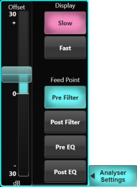
The Analyser Settings popout can be used to customise the analyser display.
- Display Slow/Fast is a global setting and determines the update rate of the analyser.
-
Feed Point Pre Filter/Post Filter/Pre EQ/Post EQ
sets the source signal for the analyser. This is a per-path setting. Note that the Filter and EQ blocks can be moved freely in the path processing order.
- Offset adjusts the level of the signal going to the analyser. This is a per-path setting. Note that this does not affect the audible signal level of the path.
Live supports the connection of multiple surfaces for remote control of its audio engine, including other console surfaces and the SOLSA PC application
(see the Remote Control section for further details).
Each 'surface' (including SOLSA) supports showing the EQ analyser on a selected path. However, the analyser is only available on one path at a time.
You may therefore wish to disable the Analyser view on surfaces other than the primary surface, to prevent other users changing which path the analyser is assigned to.
This can be done in the User Options page (MENU > Setup > Options > USER).
See the User Options section for further details and options.
Note: The analyser is only available on mono and stereo paths.
Resetting the EQ
To reset individual EQ or filter bands, press the Band Reset button to the right of the EQ graph and select the required band from the drop-down list.
To reset the entire EQ and/or filters to flat, press & hold the EQ IN or Filter IN button and select the Reset option from the drop-down list that appears.
Quick Controls
Follow Detail
The Quick Controls beneath the screen can also be assigned to the Detail View parameters.
This requires the Follow Detail button (bottom right corner of the Main Screen) to be activated.
With Follow Detail on, the Quick Controls below the screen are assigned to different functions for the selected channel
(only applicable when the Detail View is open). The Quick Controls on other Fader Tiles are unaffected.
The labels across the bottom of the Detail View indicate the functions assigned to the Quick Controls directly beneath them.
As a general rule only one function is assigned to each Channel's Quick Controls.
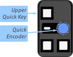
Switch functions are assigned to the Upper Quick Key (which will be lit if available) and continuous parameters are assigned to the Encoder.
Follow Channel Quick Control Mode
Tap once on the EQ section of the Channel View or the Detail View to send the Filters/EQ to the Quick Controls.
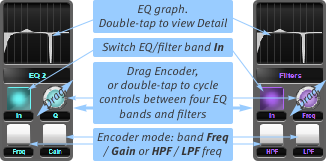
Press the Fader Tile Encoder (or double-tap the Screen Encoder) to cycle the controls between the four EQ bands (cyan) and two filter bands (purple);
Switch the EQ into circuit by pressing the In button in any of the four equaliser band pages. Similarly, to switch the filters into circuit, press the In button in the filters page;
For equaliser bands, use the bottom two Quick Control buttons to switch the Encoder's parameter between the band's frequency (left button lit), gain (right button lit) and Q (neither button lit);
For filter bands, use the bottom two Quick Control buttons to switch the Encoder's parameter between hi-pass frequency and lo-pass frequency;
Now drag the Encoder to adjust the selected parameter.
The Context display displays the current EQ settings. A simplified version of this graph is also shown in the EQ button-cap, which will stay visible when the Context Display isn't displaying EQ.
Double-tap in the Context display to open the channel EQ Detail View, where you can edit more advanced EQ parameters.
If the gain control for an EQ band is greyed out, its band is probably set to 'notch'.
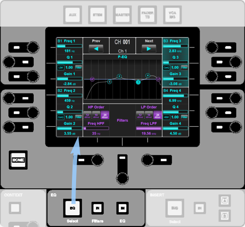
Control Tile
To switch the four EQ bands in or out, press the EQ IN button in the EQ area beneath the screen; To switch the filters in or out, touch the Filters IN button.
To reset the EQ bands or Filters, press & hold the appropriate IN button until it flashes.
The graph in the middle of the screen indicate the current EQ and filter settings.
You can also adjust the graphic using touch.
The encoders down each side of the screen are assigned to the frequency, Q and gain of the four EQ bands, as indicated in the screen area nearest to them; to change a band's EQ shape, press its Q encoder and cycle through the settings which appear below the Q value bar.
The filter frequencies are controlled at the bottom of the screen; touch the buttons above each frequency value bar to select the filter slope.
All on-screen buttons can be controlled by touching the screen.
Dynamics
All Full paths have a Compressor and a Gate/Expander.
To access the Dynamics section, open the Detail View and select the Comp Gate page.
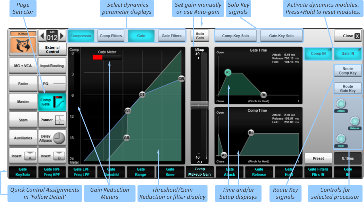
To switch the Compressor or Gate in or out, touch the Comp IN or Gate IN button (in the top-right of the page) – each button 'lights' when its dynamics element is switched in.
You can drag the nodes within the graphs displayed using a finger.
When two nodes are on top of each other, double-tap them to switch which one is selected.
To change the compressor or gate Hold value, use two fingers to pinch the Comp Time or Gate Time graph.
To change the compressor or gate (expander mode only) knee value, use two fingers to pinch the CT or GT node in the main graph.
Display Options
The buttons above the left-hand graph define which parameters are displayed, summarised as follows:
- Compressor: Threshold and Ratio on the left of the page, gain in the middle, time parameters and Compressor Setup on the right;
- Compressor AND Comp Filters: Filter frequencies on the left, Compressor gain in the middle, time parameters and Compressor Setup on the right;
- Gate: Threshold and Range on the left, time parameters and Gate Setup on the right;
- Gate AND Gate Filters: Filter frequencies on the left, time parameters and Gate Setup on the right.
- Compressor AND Gate: Both Thresholds and Ratios on the left, Compressor gain in the middle, Compressor and Gate time parameters on the right.
The Dynamics Displays
A 'traffic light' gate meter is shown in the top of the graph whenever the gate is active: Red means signal is not being passed, green means that the gate is open, and amber means the gate is at the threshold level.
The basic routing of the module is mapped in the Setup pages for each dynamics module; each element shown can be activated by touching it, and goes green to indicate that it is active.
Compressor Gain
To adjust the compressor's make-up gain manually, ensure the Compressor is active in the page, and drag the COMP slider (in the middle of the page) up and down. You will see the left-hand graph change to reflect the gain introduced.
You can also allow the console to set the make-up gain automatically: Touch the Auto Gain button (above the COMP slider) – it will 'light' to indicate that it is active, and the slider will be deactivated.
Compressor Mix Control
A Comp Mix control in the path dynamics sections provides simple access to parallel compression processing on any path.
The compressed signal can be blended in parallel with the uncompressed signal. When set to 100% only the compressed signal is used. At 0% only the dry, uncompressed signal passes. 50% provides equal contribution of compressed and uncompressed signals. The percentage can be set using the on-screen fader or associated quick control encoder when Follow Detail is enabled.
Comp Mix cannot be used when tube compressions emulation is in circuit. When Tube is engaged the mix control fader cap is removed, and mix is automatically set and shown as 100%. The previous mix percentage value is retained for when Tube is disabled.
Side-chain
The gate and compressor both have side-chains with filters and external input routing.
To insert high- and low- pass filters into the Compressor and/or Gate side-chains:
Touch the Filters button within the Compressor or Gate Setup display – it will 'light' to indicate that it is active;
Touch the Comp Filters or Gate Filters button above the left-hand graph – a frequency graph with HPF and LPF nodes will appear.
Drag the nodes to change the -3 dB points of each filter.
To route a different signal to the Compressor or Gate side-chain, touch the Comp Key Route or Gate Key Route button (to the right of the right-hand graphs) and locate the signal using the standard routing display which appears. (See Routing for instructions regarding the Routing displays.)
Now touch the Ext Key button in the Compressor or Gate Setup display to activate the external side-chain – it will 'light' to indicate that it is active.
To listen to the Compressor or Gate side-chain, touch the Comp Key Solo or Gate Key Solo button (above the right-hand graphs).
Note: The Key Listen Solo signals are routed to the Solo bus(es) specified under the channel's Misc Solo setting; see Solo for details.
Tube Emulation
You can introduce tube compressor emulation into the compression circuit:
Touch the Tube button within the Compressor Setup display – it will 'light' to indicate that it is active.
Expander Mode
The Gate can be switched into Expander mode by touching the Exp button in the Gate setup display.
Duck Mode
Engage the Duck button to turn the Gate into a Ducker.
This inverts the operation of the Gate's sidechain threshold logic, allowing the incoming signal to be attenuated by the Range amount
when the sidechain (key) input signal exceeds the Threshold, e.g. to duck the music when a DJ speaks.
Presets
To load a dynamics Preset for the channel, touch the Preset button (bottom-right of the page) and select a preset using the standard LIVE Preset page which appears.
Resetting dynamics values
To reset the compressor or gate to 1:1, press & hold the Comp IN or Gate IN button and select the Reset option from the drop-down list that appears.
Quick Controls
Follow Detail
The Quick Controls beneath the screen can also be assigned to the Detail View parameters.
This requires the Follow Detail button (bottom right corner of the Main Screen) to be activated.
With Follow Detail on, the Quick Controls below the screen are assigned to different functions for the selected channel
(only applicable when the Detail View is open). The Quick Controls on other Fader Tiles are unaffected.
The labels across the bottom of the Detail View indicate the functions assigned to the Quick Controls directly beneath them.
As a general rule only one function is assigned to each Channel's Quick Controls.
Switch functions are assigned to the Upper Quick Key (which will be lit if available) and continuous parameters are assigned to the Encoder.
Follow Channel Quick Control Mode
Tap once on the Dynamics section of the Channel View or the Detail View to send the Comp/Gate to the Quick Controls.
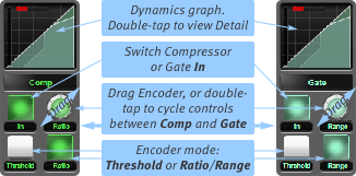
Press the Fader Tile Encoder (or double-tap the Screen Encoder) to cycle the controls between the Compressor (green) and Gate (light green);
Switch the Compressor or Gate into circuit by pressing the In button;
Use the Lower Quick Controls to switch the Encoder's parameter between CT and CR (Compressor Threshold and Ratio), or GT and GR (Gate Threshold and Range);
Now drag/turn the Encoder to adjust the dynamics.
The Context display displays the current gate and compressor settings. A simplified version of this graph is also shown in the Compressor/Gate button-cap, which will stay visible when the Context Display isn't displaying dynamics.
The actual gain reduction action is shown in the COMP and GATE meters on the console surface, to the right of the channel's fader.
Double-tap in the graph area to open the expanded display, where you can edit more advanced dynamics parameters.
Control Tile
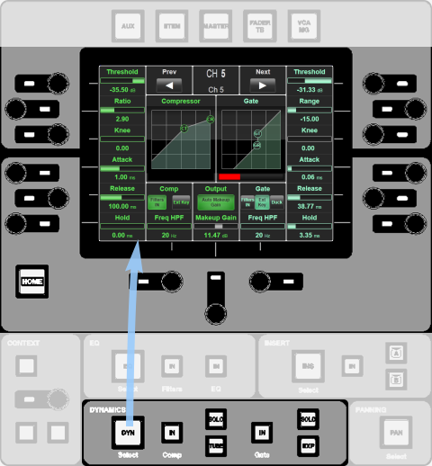
Dynamics controls can be assigned to the Control Tile (to the right of the Main Screen) by pressing the DYN button in the Dynamics area beneath the Control Tile Screen:
To switch the Compressor or Gate in or out, press the Comp or Gate IN button in the Dynamics area beneath the screen.
To reset the Compressor or Gate, press & hold the appropriate IN button until it flashes.
You can also adjust the graphic using touch.
All on-screen buttons can be controlled by touching the screen.
The encoders around the screen are assigned to the functions in the screen area nearest to them, with the compressor controls down the left and the gate controls down the right.
Switches are operated by pressing the encoder, and continuous parameters are changed by turning the encoder.
Delay
The signal on each Full Path in Live can be delayed by up to 2 seconds.
Open the Detail View and tap on the Delay All Pass page.
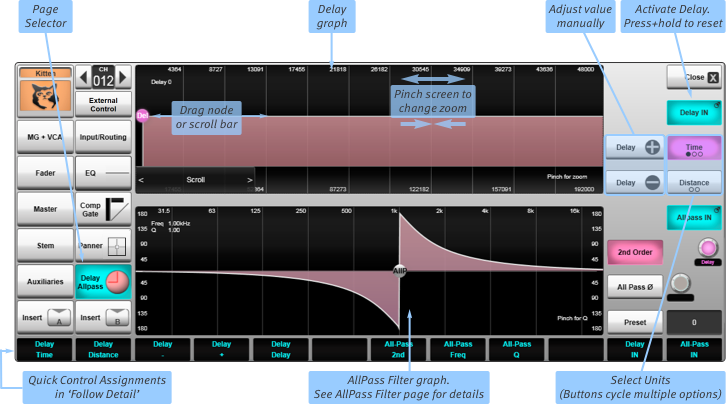
To switch the Delay in or out, touch the Delay IN button (in the top-right of the page) – the button goes blue when it is switched in.
You can drag the Del node within the graph using a finger.
There is a scrollbar below the graph. The display will scroll if you attempt to drag the node beyond the left or right border.
You can change the delay by dragging the scroller. This will leave the node in its position in the display and scroll the graph behind it.
To zoom in and out, use two fingers and draw them together or apart.
The delay amount is shown in the top left of the graph. The Time and Distance buttons to the right of the graph define the units, with each button cycling through relevant units (samples/milliseconds/seconds, and centimetres/metres).
Note: The delay value is always stored in samples. Changing the sample rate of the console will alter the delay time in other units.
To set a precise delay amounts you can use the Delay Time – and + buttons below the unit buttons to increment the delay by a sample at a time. Alternatively, select the Del node, double-tap the value box in the bottom right corner and use the keyboard which appears.
Tip: You may find the following to be the most efficient way to operate the graph:
- Zoom in quite close on the graph and leave the Del node in the centre;
- Use the Scroller to set the rough delay value;
- Now move the Del node to perform fine adjustments to the value.
Note: The path delay is used for delaying the entire signal, not for creating delay effects. Delay effects can be routed to the path inserts from the console's effects engine. See Effects Racks for more details.
Quick Controls
Follow Detail
The Quick Controls beneath the screen can also be assigned to the Detail View parameters. This requires the Follow Detail button (bottom right corner of the Main Screen) to be activated. Touch the button to toggle between:
The Quick Controls below the screen are assigned to different functions for the selected channel
(only applicable when the Detail View is open). The Quick Controls on other Fader Tiles are unaffected.
The labels across the bottom of the Detail View indicate the functions assigned to the Quick Controls directly beneath them. As a general rule only one function is assigned to each Channel's Quick Controls. Switch functions are assigned to the Upper Quick Key (which will be lit if available) and continuous parameters are assigned to the Encoder.
To reset the delay unit to 0, press & hold the Delay IN button (in the Detail View) and select the Reset option from the drop-down list that appears.
To close the Detail View, touch the Close button in the top right-hand corner.
Follow Channel Quick Control Mode
Tap once on the Delay section of the Channel View or the Detail View to send the Delay/All Pass to the Quick Controls.
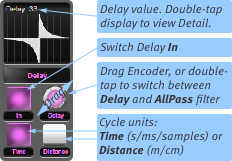
Press the Fader Tile Encoder (or double-tap the Screen Encoder) to cycle the controls between the Delay (magenta) and All Pass (pink);
Switch the Delay or All Pass into circuit by pressing the In button;
Turn the Encoder to adjust the delay.
The delay amount is shown above the Quick Key display. The lower Quick Keys switch between
Time and Distance measurements,
with each button cycling through relevant units (samples/milliseconds/seconds, and centimetres/metres).
Control Tile
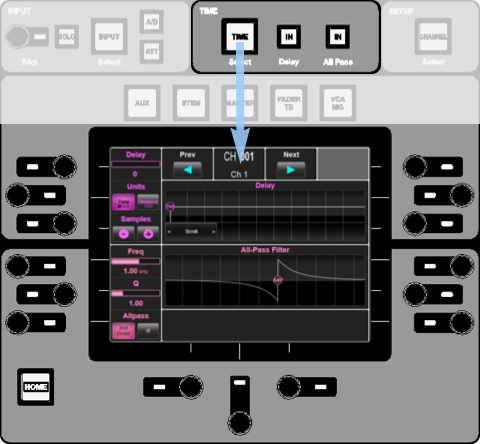
To switch the delay in or out, press the Delay IN button in the Time area above the screen.
To reset the delay, press & hold the IN button until it flashes.
Delay controls are assigned to the top half of the screen, with All Pass filter controls assigned to the bottom half.
The delay amount is shown in the top left of the screen, and can be changed using the encoder to its left.
The Time and Distance buttons below that define the units; press the adjacent encoder to cycle through all relevant units (samples/milliseconds/seconds, and centimetres/metres). You can also press these buttons directly in the screen.
The Samples – and + buttons allow you to make incremental changes to the delay value.
The Delay graph indicates the current settings.
You can drag the Del (delay) node within the graph using a finger.
The display will scroll if you attempt to drag the node beyond the left or right border.
You can also change the delay by dragging the scroller beneath the graph; this will leave the node in its position in the display and scroll the graph behind it.
To zoom in and out, use two fingers and draw them together or apart.
All Pass Filter
The All Pass Filter can be used to adjust the phase of a specific range of frequencies.
The All Pass Filter is particularly useful to solve feedback issues in wedge monitors or when working with multiple microphones on the same instrument.
A simple Ø invert button is most useful in situations where the phase relationship of two signals is close to exactly opposite, but often this is not the case.
The All Pass Filter is a far more accurate tool to solve phase-related issues.
Open the Detail View and tap on the Delay All Pass button.
To switch the All Pass Filter in or out, touch the All Pass IN button (in the top-right of the page) – the button goes blue when it is switched in.
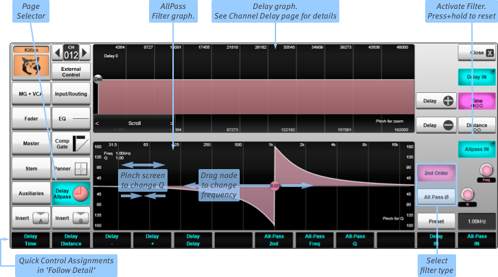
Define the filter type using the 2nd Order and All Pass Ø buttons.
You can drag the AllP node within the graph using a finger or the mouse button.
To change the Q (when in 2nd order), use the pinch gesture.
The filter's Q and centre frequency are shown in the top left of the graph.
To reset the filter to its default values, press & hold the All Pass IN button (in the Detail View) and select the Reset option from the drop-down list that appears.
Quick Controls
Follow Detail
The Quick Controls beneath the screen can also be assigned to the Detail View parameters. This requires the Follow Detail button (bottom right corner of the Main Screen) to be activated. Touch the button to toggle between:
The Quick Controls below the screen are assigned to different functions for the selected channel (only applicable when the Detail View is open).
The Quick Controls on other Fader Tiles are unaffected.
The labels across the bottom of the Detail View indicate the functions assigned to the Quick Controls directly beneath them.
As a general rule only one function is assigned to each Channel's Quick Controls. Switch functions are assigned to the Upper Quick Key (which will be lit if available) and continuous parameters are assigned to the Encoder.
Follow Channel Quick Control Mode
Tap once on the Delay section of the Channel View or the Detail View to send the Delay/All Pass to the Quick Controls.
Press the Fader Tile Encoder (or double-tap the Screen Encoder) to cycle the controls between the Delay (magenta) and All Pass (pink);
Switch the Delay or All Pass into circuit by pressing the In button;
Turn the Encoder to adjust the frequency.
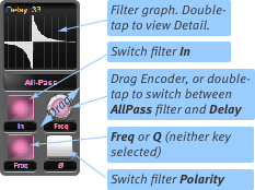
The channel Quick Controls cycle between Delay and All Pass filter controls – press the Fader Tile Encoder (or double-tap the on-screen Encoder) to switch to the correct display.
In the All Pass display, switch the filter into circuit by pressing the In button.
The lower left button (Freq) define the parameter assigned to the encoder;
if it is deselected, the Encoder controls the filter's Q.
The lower right button controls the All Pass Ø button.
Control Tile
All Pass filter controls can be assigned to the Control Tile by pressing the Time button above the Control Tile Screen:
To switch the All Pass filter in or out, press the AllPass IN button in the Time area above the screen.
To reset the All Pass filter, press and hold the IN button until it flashes.
Filter controls are assigned to the bottom half of the screen, with Delay controls assigned to the top half.
Encoders to the left of the All-Pass Filter graph can be used to change the filter frequency and Q, as indicated by the value bars adjacent to them inside the screen.
You can also drag the AllP node left or right to change the centre frequency.
Buttons in the bottom left corner allow you to change the order and phase of the filter.

